...Something's wrong!
hi, could be that one or more model not working, disable one by one to isolate the fault.
Thanks, I'll try that. I'm going to have to look at the way I originally named the models in the tube.lib file. Maybe Spice looks for the symbol first, and then connects it to the model in tube.lib.hi, could be that one or more model not working, disable one by one to isolate the fault.
Last edited:
Hi, AdrianHi Koonw
Well done!
For negative Vg, there are no significant differences to mine. for positive Vg, your plate current is more accurate while my grid current is more accurate.
Congratulations!
Thank you for your advice and complement. The grid current other than scope published esp below 0, there is no reference, so it could be out. I am curious how you adjust this grid current ? Looks it's over compensated: I attached some files for your advice, as I can also update my model if confirmed right, thanks.
Attachments
I'm doing what you suggested, and it seems I have a problem with my .subckt and Symbol file naming convention. When I called up a 6SN7 model of any version, LTSpice was defaulting to the original generic .subckt in the tube.lib file. I knocked out all the 6SN7 models and their associated ASY files except Adrian's, and it called up the correct model. Now I'm seeing the difference with Adrian's model.hi, could be that one or more model not working, disable one by one to isolate the fault.
If I can't solve this on my own, I'll scoot on over to the "Installing LTSpice....." thread, and throw myself at the mercy of the good folks over there. Thanks for the suggestion.
Hi, Adrian
Thank you for your advice and complement. The grid current other than scope published esp below 0, there is no reference, so it could be out. I am curious how you adjust this grid current ? Looks it's over compensated: I attached some files for your advice, as I can also update my model if confirmed right, thanks.
Hi Koonw
There is for almost every triode a significant grid current at Vg=0V, that is really plausible. Ig will vanish only to ignorable amounts when the grid voltage is at least -1V or even more negative.
But I 'm missing a grid current trace for Vg=0V to adjust the model for best accuracy. Instead, I have to "extrapolate" backwards from the 4, 8 ,12 etc traces - so, for the grid-cathode vacuum diode's contact voltage, it is not easy to find the current value. I just took over the plate current model's contact voltage.
When I find time, I maybe do a least mean square fit of the grid-cathode vacuum diode, to find more precise values of the grids params.
all the best, Adrian
Koonw,
the principle descibled in your link is applied in the car tube 12K5, a special tetrode where the first grid is intended to get out more electrones from the cathode, because the anode has only 12v in a car. For current modulation, the second grid is used. Super interesting principle!
the principle descibled in your link is applied in the car tube 12K5, a special tetrode where the first grid is intended to get out more electrones from the cathode, because the anode has only 12v in a car. For current modulation, the second grid is used. Super interesting principle!
Koonw, I've been barking up the wrong tree for the whole day. I cannot get either Adrian's model or your one to work at all in LTSpice. I need to ask this important question: what should I name the .ASY symbol file for your model?hi, could be that one or more model not working, disable one by one to isolate the fault.
You name triode asy "6SN7_RY", as found in my model e.g :Koonw, I've been barking up the wrong tree for the whole day. I cannot get either Adrian's model or your one to work at all in LTSpice. I need to ask this important question: what should I name the .ASY symbol file for your model?
.SUBCKT 6SN7_RY 1 2 3 ; Plate Grid Cathode in the model
or "6SN7WGT.RAi4" as in Adrian
.subckt 6SN7WGT.RAi4 A G K
You can change to any other name but both should be same in asy and model
Yes, I've been doing that. I obviously have a different problem. I'll continue investigations. Thanks.You name triode asy "6SN7_RY", as found in my model e.g :
.SUBCKT 6SN7_RY 1 2 3 ; Plate Grid Cathode in the model
or "6SN7WGT.RAi4" as in Adrian
.subckt 6SN7WGT.RAi4 A G K
You can change to any other name but both should be same in asy and model
Download Windows version here:How to run curve captor on win 10?
Download Curve Captor from SourceForge.net
Extract and run "curvecaptor.tcl" (from Dos prompt or Explorer), if you haven't got ActiveTcl, download and install it first.
Download and Install Tcl: ActiveTcl | ActiveState
CurveCaptor then looks for a curve image file such as bmp png gif.
Watch how to trace the curve and build the Spice model:
You can save the marker and reopen to go back if you make mistakes.
YouTube
Watch this how to plot the curve just built:
YouTube
Thank you, tcl works, but it would not load any image, I've tried png bmp jpgDownload Windows version here:
Download Curve Captor from SourceForge.net
Extract and run "curvecaptor.tcl" (from Dos prompt or Explorer), if you haven't got ActiveTcl, download and install it first.
Download and Install Tcl: ActiveTcl | ActiveState
CurveCaptor then looks for a curve image file such as bmp png gif.
Watch how to trace the curve and build the Spice model:
You can save the marker and reopen to go back if you make mistakes.
YouTube
Watch this how to plot the curve just built:
YouTube
error is - file not found
Attachments
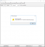
Thank you, tcl works, but it would not load any image, I've tried png bmp jpg
error is - file not found
Oh true it wouldn't open file with jpg extension maybe because license issue but surely you can convert to other format using Paint Brush, it should open png and gif.
Last edited:
Morgan Jones - Building valve amplifiers
"Beam valves and mains transformers. Beam valves deliberately focus their current into thin sheets that pass largely unintercepted between the horizontal wires... "
What does that "beam valves" mean?
Edit: nevermind, (of course) after posting I have found it: Beam deflection tube - Wikipedia
But why I need this in a tube amplifier? I cannot imagine.
Last edited:
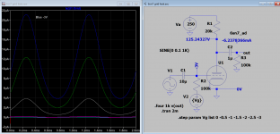
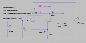
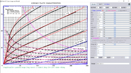
I have had terrible difficulty loading different models for the 6SN7 into LTSpice. It's basically a naming problem. When I load more than one model for this tube, having named the corresponding .asy symbol file to match the name that follows .SUBCKT in the tube.lib file, LTSpice gives me a message to say "unknown subcircuit". To obtain my symbol files for the various models, I had copied the Koren Modified symbol file ("6SN7.asy") which came with the batch I downloaded, and renamed it appropriately, i.e. "6SN7_RY.asy" or "6SN7WGT.RAi4.asy" or to whatever I needed. I then simply inserted them into the sym/Tubes/Triodes folder, and left the original ("6SN7.asy") also in place.I would recommend to drive a.dc simulation, e.g. like that:
.dc Va 0 250 1 Vg -24 6 2 (see attached picture)
with all the 6SN7 models you have, in parallel connected.
This way, you will easy see the differences of the models.
cheers, Adrian
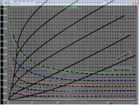
In order to run the 4 different 6SN7 simulations, I needed to leave the original 6SN7.asy in situ, and remove all the others. I then had to edit the appropriate tube name directly following .SUBCKT in the "tube.lib" file to read just "6SN7". So, "6SN7WGT.RAi4" became just plain old "6SN7", and so on and on. Then each model needed to be added in turn, while removing the previous model each time. To get the simulation to run, there needed to be just one 6SN7 model only in "tube.lib", and just one .asy symbol file in the Triode sym folder. I cannot figure this problem out, but after a good few hours work, I have run the 4 different model simulations for Fourier analysis and THD. The results speak for themselves. I suspected that the Koren Modified model was giving a suspiciously low figure for THD. Anyway, here are the results:
Attachments
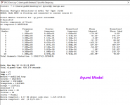
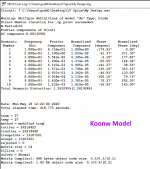
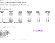
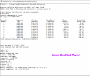
There is little difference in Adrian model plot and mine except grid current, Ayumi model has grid current model also but may be absent from Koren model. so I think the different is mainly in grid current model.
I sympathize with you regard your problem, as most people could have the same problem with data running multiple model for comparison.
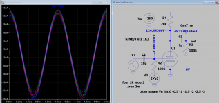
I found a quick solution to run multiple model from one schematic:
Make a copy of model file and give it a number instead of tube name following .subckt in the model e.g.
6sn7_ry becomes 1, 6SN7WGT.RAi4 become 2, 6sn7 become 3 and so on.
Then name the triode asy as {Tube} and now can step over the list :
.step param Tube list 1 2 3
Now all models plots (and err log) can be seen on one screen or file. This is extremely convenient for virtual comparison and time saving.
I sympathize with you regard your problem, as most people could have the same problem with data running multiple model for comparison.
I found a quick solution to run multiple model from one schematic:
Make a copy of model file and give it a number instead of tube name following .subckt in the model e.g.
6sn7_ry becomes 1, 6SN7WGT.RAi4 become 2, 6sn7 become 3 and so on.
Then name the triode asy as {Tube} and now can step over the list :
.step param Tube list 1 2 3
Now all models plots (and err log) can be seen on one screen or file. This is extremely convenient for virtual comparison and time saving.
Last edited:
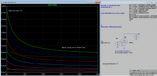
Thanks for that advice. I've been working on it for almost two days. So I'll start afresh tomorrow. I'm mainly interested in working with this tube for driving the 300B, even though it gets a lot of criticism from DIYers who prefer more sophisticated solutions, but I like the simple approach. I am using a IXCP10M90S as a plate load - you can see that the gain is almost mu. BTW, I must knock out one of the paralleled tubes and see how the results compare. I will use your model to do this at first.There is little difference in Adrian model plot and mine except grid current, Ayumi model has grid current model also but may be absent from Koren model. so I think the different is mainly in grid current model.
I sympathize with you regard your problem, as most people could have the same problem with data running multiple model for comparison.
I found a quick solution to run multiple model from one schematic:
Make a copy of model file and give it a number instead of tube name following .subckt in the model e.g.
6sn7_ry becomes 1, 6SN7WGT.RAi4 become 2, 6sn7 become 3 and so on.
Then name the triode asy as {Tube} and now can step over the list :
.step param Tube list 1 2 3
Now all models plots (and err log) can be seen on one screen or file. This is extremely convenient for virtual comparison and time saving.
Here is an update for Raytheon 6sn7 mainly readjusted the grid current, between +20V and 0 it compared quite well with actual curve, but between 0 and -2v, there is some difference between this model and Adrian's, e.g at 0, by about 1.5mA. The grid positive threshold VgOff is set to -2.5V, so it doesn't process grid current beyond this point.
Code:
**** 6SN7_RY ** Advanced Grid Current **********************************
* Created on 05/19/2020 05:46 using paint_kit.jar 3.1
* [URL="http://www.dmitrynizh.com/tubeparams_image.htm"]Model Paint Tools: Trace Tube Parameters over Plate Curves, Interactively[/URL]
* Plate Curves image file: 6sn7-ry.png
* Data source link:
*----------------------------------------------------------------------------------
.SUBCKT 6SN7_RY 1 2 3 ; Plate Grid Cathode
+ PARAMS: CCG=2.2P  CGP=3.7P CCP=0.7P
+ MU=20.37 KG1=2019.77 KP=176.44 KVB=500 VCT=0.3374 EX=1.4
+ VGOFF=-2.5 IGA=0.006879 IGB=0.3606 IGC=18.64 IGEX=1.534
* Vp_MAX=250 Ip_MAX=87.5 Vg_step=4 Vg_start=20 Vg_count=11
* Rp=4000 Vg_ac=55 P_max=5 Vg_qui=-48 Vp_qui=300
* X_MIN=32 Y_MIN=35 X_SIZE=820 Y_SIZE=575 FSZ_X=1296 FSZ_Y=736 XYGrid=false
* showLoadLine=n showIp=y isDHT=n isPP=n isAsymPP=n showDissipLimit=y
* showIg1=y gridLevel2=y isInputSnapped=n
* XYProjections=n harmonicPlot=n dissipPlot=n
*----------------------------------------------------------------------------------
E1 7 0 VALUE={V(1,3)/KP*LOG(1+EXP(KP*(1/MU+(VCT+V(2,3))/SQRT(KVB+V(1,3)*V(1,3)))))}
RE1 7 0 1G  ; TO AVOID FLOATING NODES
G1 1 3 VALUE={(PWR(V(7),EX)+PWRS(V(7),EX))/KG1}
RCP 1 3 1G   ; TO AVOID FLOATING NODES
C1 2 3 {CCG} ; CATHODE-GRID
C2 2 1 {CGP} ; GRID=PLATE
C3 1 3 {CCP} ; CATHODE-PLATE
RE2 2 0 1G
EGC 8 0 VALUE={V(2,3)-VGOFF} ; POSITIVE GRID THRESHOLD
GG 2 3 VALUE={(IGA+IGB/(IGC+V(1,3)))*(MU/KG1)*(PWR(V(8),IGEX)+PWRS(V(8),IGEX))}
.ENDS
*$
Attachments
Last edited:
Hi Koonw
There is for almost every triode a significant grid current at Vg=0V, that is really plausible. Ig will vanish only to ignorable amounts when the grid voltage is at least -1V or even more negative.
But I 'm missing a grid current trace for Vg=0V to adjust the model for best accuracy. Instead, I have to "extrapolate" backwards from the 4, 8 ,12 etc traces - so, for the grid-cathode vacuum diode's contact voltage, it is not easy to find the current value. I just took over the plate current model's contact voltage.
When I find time, I maybe do a least mean square fit of the grid-cathode vacuum diode, to find more precise values of the grids params.
all the best, Adrian
Hi all,
As mentioned above, here is a refined Raytheon 6SN7 model of mine. I shorted the new model's name to more readable 6SN7.RAi4, as there is only one Raytheon datasheet on frank's site, so no risk of mix-up...
Let me give some explanations to the steps I did:
1) First of all, one have to know that the grid current consists of two indepedant parts, one is a simple vacuum diode according the famous langmuir-chlild's law. The other part is a fraction of the space charge current, which is for high Va mainly assigned to the plate, and with smooth transition is more and more assigned to the grid when Va drops toward zero.
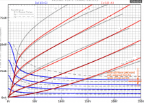
To readjust the grid's vacuum diode, we therefore use the grid currents at highest possible Va found in the diagramm. In the first picture, you see the currents I found by detailed analysis of a zoomed graph part.
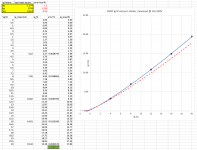
2) Next step was a least mean square fit in excel (see the yellow values), based on the previous found values for the grids vacuum diode, see second picture.
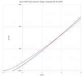
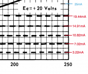
3) Be aware that even @ Va=250V, a small part of the diagramms grid current belongs to the space charge current, while we assumed that it is "pure vacuum diode current" in our excel fit. That's why the models Ig is a bit to high when just overtake the params found in the excel, see third picture.
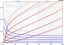
4) So we readjust the vacuum diodes gain factor kg a bit - and finished this job! 😀😀
The improved grid current compared to the old model is shown in the fourth picture (blue=new, red=old)
cheers, Adrian
Code:
*6SN7 LTspice model based on the generic triode model from Adrian Immler, version i4
*A version log is at the end of this file
*Params fitted to the Raytheon 6SN7WGT datasheet by Adrian Immler, May 2020
*The high fit quality is presented at adrianimmler.simplesite.com
*History's best of tube decribing art (plus some new ideas) is merged to this new approach.
*@ neg. Vg, Ia accuracy is similar to Koren or Ayumi models.
*@ small neg. Vg, the "Anlauf" current is considered.
*@ pos. Vg, Ig and Ia accuracy is on a unrivaled level.
*This offers new simulation possibilities like bias point setting with MOhm grid resistor,
*Audion radio circuits, low voltage amps, guitar distortion stages or pulsed stages.
*                 anode (plate)
*                 | grid
*                 | | cathode
*                 | | |
.subckt 6SN7.RAi4 A G K
.params
*Parameters for the space charge current @ Vg <= 0
+ mu   = 21.3 ;Determines the voltage gain @ constant Ia
+ rad  = 6k2  ;Differential anode resistance, set @ Iad and Vg=0V
+ Vct  = 0.83 ;Offsets the Ia-traces on the Va axis. Electrode material's contact potential
+ kp   = 147  ;Mimics the island effect
+ xs   = 1.5  ;Determines the curve of the Ia traces. Typically between 1.2 and 1.8
*
*Parameters for assigning the space charge current to Ia and Ig @ Vg > 0
+ kB   = 0.14 ;Describes how fast Ia drops to zero when Va approaches zero.
+ radl = 370  ;Differential resistance for the Ia emission limit @ very small Va and Vg > 0
+ tsh  = 10   ;Ia transmission sharpness from 1th to 2nd Ia area. Keep between 3 and 20. Start with 20.
+ xl   = 1.5  ;Exponent for the emission limit
*
*Parameters of the grid-cathode vacuum diode
+ kvdg  = 188 ;virtual vacuumdiode. Causes an Ia reduction @ Ig > 0.
+ kg = 2k     ;Inverse scaling factor for the Va independent part of Ig (caution - interacts with xg!)
+ Vctg = 0.513;Offsets the log Ig-traces on the Vg axis. Electrode material's contact potential
+ xg   = 1.174;Determines the curve of the Ig slope versus (positive) Vg and Va >> 0
+ VT   = 0.1  ;Log(Ig) slope @ Vg<0. VT=k/q*Tk (cathodes absolute temp, typically 1150K)
+ Vft2 = 0 gft2 = 7  ;finetunes the gridcurrent @ low Va and Vg near zero
*
*Parameters for the caps
+ cag  = 3p7  ;From datasheet
+ cak  = 0p8  ;From datasheet
+ cgk  = 2p5  ;From datasheet
*
*special purpose parameters
+ os = 1      ;Overall scaling factor, if a user wishes to simulate manufacturing tolerances
*
*Calculated parameters
+ Iad = 100/rad  ;Ia where the anode a.c. resistance is set according to rad.
+ ks = pow(mu/(rad*xs*Iad**(1-1/xs)),-xs) ;Reduces the unwished xs influence to the Ia slope
+ ksnom = pow(mu/(rad*1.5*Iad**(1-1/1.5)),-1.5) ;Sub-equation for calculating Vg0
+ Vg0 = Vct + (Iad*ks)**(1/xs) - (Iad*ksnom)**(2/3) ;Reduces the xs influence to Vct.
+ kl = pow(1/(radl*xl*Ild**(1-1/xl)),-xl) ;Reduces the xl influence to the Ia slope @ small Va
+ Ild = sqrt(radl)*1m ;Current where the Il a.c. resistance is set according to radl.
*
*Space charge current model
Bggi GGi 0 V=v(Gi,K)+Vg0 ;Effective internal grid voltage.
Bahc Ahc 0 V=uramp(v(A,K)) ;Anode voltage, hard cut to zero @ neg. value
Bst   St 0 V=uramp(max(v(GGi)+v(A,K)/(mu), v(A,K)/kp*ln(1+exp(kp*(1/mu+v(GGi)/(1+v(Ahc)))))));Steering volt.
Bs    Ai K I=os/ks*pow(v(St),xs) ;Langmuir-Childs law for the space charge current Is
*
*Anode current limit @ small Va
.func smin(z,y,k) {pow(pow(z+1f, -k)+pow(y+1f, -k), -1/k)} ;Min-function with smooth trans.
Ra  A Ai 1
Bgl Gi A I=min(i(Ra)-smin(1/kl*pow(v(Ahc),xl),i(Ra),tsh),i(Bgvd)*exp(4*v(G,K))) ;Ia emission limit
*
*Grid model
Bvdg G Gi I=1/kvdg*pwrs(v(G,Gi),1.5) ;Reduces the internal effective grid voltage when Ig rises
Rgip G Gi 1G ;avoids some warnings
.func Ivd(Vvd, kvd, xvd, VTvd)  {if(Vvd < 3, 1/kvd*pow(VTvd*xvd*ln(1+exp(Vvd/VTvd/xvd)),xvd), 1/kvd*pow(Vvd, xvd))} ;Vacuum diode function
Bgvd Gi K I=Ivd(v(G,K) + Vctg - uramp(-v(A,K)/mu), kg/os, xg, VT)
.func ft2() {gft2*(1-tanh(3*(v(G,K)+Vft2)))} ;Finetuning-func. improves ig-fit @ Vg near -0.5V, low Va.
Bgr Gi Ai I=ivd(v(GGi),ks/os, xs, 0.8*VT)/(1+ft2()+kB*v(Ahc));Is reflection to grid when Va approaches zero
Bs0 Ai K  I=ivd(v(GGi),ks/os, xs, 0.8*VT)/(1+ft2()) - os/ks*pow(v(GGi),xs) ;Compensates neg Ia @ small Va and Vg near zero
*
*Caps
C1 A G {cag}
C2 A K {cak}
C3 G K {cgk}
.ends
*
*Version log
*i1 :Initial version
*i2 :Pin order changed to the more common order „A G K“ (Thanks to Markus Gyger for his tip)
*i3 :bugfix of the Ivd-function: now also usable for larger Vvd
*i4: Rgi replaced by a virtual vacuum diode (better convergence). ft1 deleted (no longer needed)
;2 new prarams for Ig finetuning @ Va and Vg near zero. New overall skaling factor os for aging etc.
Attachments
Last edited:
- Home
- Amplifiers
- Tubes / Valves
- Vacuum Tube SPICE Models