mbrennwa,
You have built a unique looking amplifier - congratulations, and enjoy the sound!
And thanks for sharing the measurements.
You have built a unique looking amplifier - congratulations, and enjoy the sound!
And thanks for sharing the measurements.
View attachment 904248
If you experience bright / edgy / harshness with this amp design, flip the polarity on your source or at the speaker terminal. I can guarantee a different result.
This design has a lot of really nice qualities that make it good long-term amplification: conciseness with warmth.
😀
Wow, I use a Korg Nutube and flipped the wires at the speaker end per Nelson's article. But never tried in the right polarity, after your post I am going to try that too and see 🙂
Thanks
Wow, I use a Korg Nutube and flipped the wires at the speaker end per Nelson's article. But never tried in the right polarity, after your post I am going to try that too and see 🙂
Thanks
Yeah, you have to try those different permutations of polarity to see what happens. Also, this is the kind of design that is the classic "garbage in, garbage out": if it's a brittle sounding source, it will brittle out of this amp. More specifically, this amp sounds like the source.
I drive this amp with one of two tube output dacs, with nothing in-between, and I can change tubes to suit my taste. Some tubes in the chain are unlistenable (too warm or too hard sounding), while others are just perfect. That is brilliance of having a tube in the chain.
I drive this amp with one of two tube output dacs, with nothing in-between,....
No volume control!?
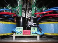
Hi nikosokeyThese days I placed at the entrance of the transformers the small board dc trap now quiet forever, velvety sound accompanied by the DCG3 preamplifier.
I am glad you could completely remove the hum. Personally velvet sound is also my preference.
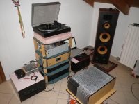
It is always informative to know what other gear people uses in their system. 🙂
Fab
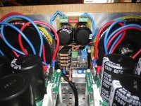
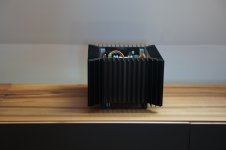
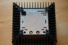
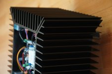
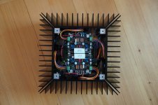
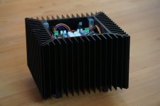
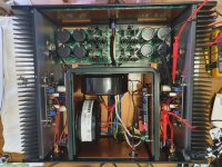
Here are some better photos of my build. The amp is still running topless, just because I think it's cool. I'll put on the top lid when the cat becomes too curious.
Attachments
This is a very nice looking amplifier Mbrennwa. 🙂
Thanks for posting.
At the end what is the bias current you are able to manage with this small size class A amplifier but with efficient heatsinks use ( 4 sides instead of usually only 2 ) ?
Fab
Thanks for posting.
At the end what is the bias current you are able to manage with this small size class A amplifier but with efficient heatsinks use ( 4 sides instead of usually only 2 ) ?
Fab
I was running it the USSA at +/- 25.5 VDC with 1.5 A for a while, and it was pretty hot. My Aleph uses the same chassis at +/- 23 VDC with 1.8 A, and its borderline hot.This is a very nice looking amplifier Mbrennwa. 🙂
Thanks for posting.
At the end what is the bias current you are able to manage with this small size class A amplifier but with efficient heatsinks use ( 4 sides instead of usually only 2 ) ?
Fab
Hi Fab,
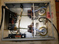
It's been a while, late 2018, but I am back to getting this amp finalised. Before I got busy I had just calculated and installed RV1a and RV2a and stuffed things in a box I had built. Not even enough time to adjust the bias or DC offset...which is where I got to last night some two years later.
Right channel was easy to set at 65mA across R15 with DC offset virtually zero. All good it seems.
Left channel I can set 65mA but the DC offset is about 8V (yes volts) and winding the trimpot from one extreme to the other changes this insignificantly if at all. Frustrating! Is this something you are able to easily diagnose? My familiarity with the build has left me over the past two years and I am trying to avoid a lengthy investigation or going back to the start.
Anthony
Attachments
Hi acg
For the channel with issue,You can redo all measurements from the manual again. Here is an extract:
8.7 Current sources adjustment
Adjust P3 for 28mv between TP9 and TP10.
Adjust P4 for 28mV between TP11 and TP12.
8.8.5 Adjust current in input stage
Measure voltage between TP8 and V-.(TP4)
Measure voltage between TP7 and V+. (TP2)
8.14 Front End amplifier testing
Connect V+ and V- and PGND (the one close to V-) to power supply (from 15Vdc to 30Vdc).
Adjust P1 for about 0,3Vdc between TP6 and V-(TP4)
Adjust P2 for about 0,3Vdc between TP5 and V+(TP2)
8.17 Output Mosfet VGS determination
Measure voltage between TP6 and V- (TP4) (VGSN = ________)
Measure voltage between TP5 and V+ (TP2) (VGSP = ________)
9 Test assembled board (no load)
Install the meter probe leads between TP1 and TP2 and measure voltage
Install the meter probe leads between TP3 and TP4) and measure voltage
Report all voltages.
Fab
Hi acg
For the channel with issue,You can redo all measurements from the manual again. Here is an extract ( I have removed a redundant part).
If you have 65mv across R15 then you cannot have also 65mv across R16 if you have such extreme DC at output.🙁
Have you checked for shorted D2 and D4?
8.7 Current sources adjustment
Adjust P3 for 28mv between TP9 and TP10.
Adjust P4 for 28mV between TP11 and TP12.
8.8.5 Adjust current in input stage
Measure voltage between TP8 and V-.(TP4)
Measure voltage between TP7 and V+. (TP2)
8.17 Output Mosfet VGS determination
Measure voltage between TP6 and V- (TP4) (VGSN = ________)
Measure voltage between TP5 and V+ (TP2) (VGSP = ________)
9 Test assembled board (no load)
Install the meter probe leads between TP1 and TP2 and measure voltage
Install the meter probe leads between TP3 and TP4) and measure voltage
Report all voltages.
P.s. by the way nice build!
Fab
Last edited:
Hi acg
Have you disconnected the speaker protection to prevent any possible DC protection board input circuit failure to provide DC at amplifier output ?
Fab
Have you disconnected the speaker protection to prevent any possible DC protection board input circuit failure to provide DC at amplifier output ?
Fab
Hi acg
If you have 65mv across R15 then you cannot have also 65mv across R16 if you have such extreme DC at output.🙁
Have you checked for shorted D2 and D4?
Thanks Fab.
So I have started debugging.
(1) Both bipolar PS's have about the same voltages on their rails. Good.
(2) Both R15 and R16 have the same voltage drop across them even with 8Vdc on the ouputs. Mmmm, that's not right. Previously I had been measuring just the one resistor, but both go up and down in tandem as the amp warms up.
(3) The problem channel has 21V at the speaker protection circuit. The good channel has 8V. As you suggest it might be time to make sure the speaker protection is not causing the problem. I shall investigate further.
acg, maybe my "alternative recipe" for adjusting the operating points is also useful for debugging, see here: USSA-5 Build with Review
- Home
- Amplifiers
- Solid State
- USSA-5 Build with Review