DC coupling caps and cables are a never ending story.
If you have a source with no DC, you can do a simple test: just hook up a jumper wire across the leads of the input cap and try to hear the difference. I did this with my Aleph J running off a transformer volume control (TVC), which is a-priori free of any DC. I tried hard, but I could not hear any difference with / without the input cap (Wima MKP). I will do the same test with my USSA once I have it ready.
The only obvious capacitor sound I ever experienced was when I tried the Mundorf Silver-Gold-Oil-Unicornpee caps in the xovers of the Open Source Monkey Coffin speakers. The caps were expensive, and the sound was unbearably bad.
That said, I believe that DC blocking caps in low-current applications (like in the input stage of an amplifier) may be much less critical and in a loudspeaker xover, where larger currents are involved. I guess you shouldn't loose your sleep over the choice of the input coupling cap as long as you stay away from Unicorn stuff. 😀
Thanks mbrennwa and I totally understand where you are coming from 😉 Unless the cost of the caps is bearable I do try it out sometimes but otherwise just leave it at that for a sound sleep.
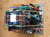
I made some progress with my build. The attached photo shows the insides of my 3D puzzle. I have done prettier builds in the past, but this one is quite challenging because my chassis is really tight, and it's hard to get access to things once the boards are in...
From botton to top: mains transformer, 2 x Smooth Like Buttah PSU boards, 2 x USSA-5 boards. XRK SSR DC protection boards on the sides.
When I turned it on, the magic smoke came out. I'll have to put it some fresh smoke, but I need a break first.
From botton to top: mains transformer, 2 x Smooth Like Buttah PSU boards, 2 x USSA-5 boards. XRK SSR DC protection boards on the sides.
When I turned it on, the magic smoke came out. I'll have to put it some fresh smoke, but I need a break first.
Attachments

Hi Mbrennwa,
That’s a cool looking spacecraft you are building there!
In satellite business, before we button things up tight like this, we build it all on a table (or plywood plank in my case when doing amps) and this is called a “FlatSat” build. When that works without magic smoke or noise/hum, we can work on shoehorning it into a small box.
You may need to flatten this build to debug section by section.
It looks way cool though! 😎
Yeah, I did the flat sat first, except that it was more "flying" than flat. And I took a shortcut by not installing the DC SSR boards. Those boards are super easy to work with, and I have used them before, so I left them out for the test run. However, in the shoehorn build it was also easy to connect the SSR boards to the PSU with wrong polarity... thats where smoke happened. Luckily I have some spare boards, so it should be an easy fix.
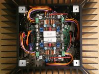
It's in! No smoke so far. Warming up...
Nice! Where'd you get that urchin-style OG Aleph chassis?
Ok, the amp is now biased at 1.5A idle, running at +/- 25.9 V rails. The chassis gets nice and warm like this, but not too hot. Output DC is very stable to within single-digit millivolt values.
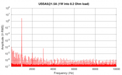
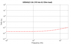
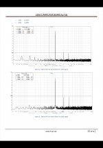
Harmonic distortion is a bit lower than at the "standard" 1A bias. I attached some measurements (images are examples measured at 1W into 8.2 Ohm, many more in the ZIP attachment).
Output impedance is 0.14 Ohm (measured at 100 Hz), which corresponds to a damping factor of 57 into an 8 Ohm load. This is a bit higher than the spec in the manual (35 to 45) because I biased the amp quite a bit hotter.
This all looks pretty good to me. Next step is to listen to it, but I first need to fix my workshop dummy speakers... 🙄
Attachments
Nice work Mbrennwa!
You successfully packed 50lbs of potatoes into a 25lb sack 😀
The stability of your USSA5 with the utilization of “flying leads” for devices will open new options for future builds.
Time to Listen and Enjoy 🙂
You successfully packed 50lbs of potatoes into a 25lb sack 😀
The stability of your USSA5 with the utilization of “flying leads” for devices will open new options for future builds.
Time to Listen and Enjoy 🙂
Mbrennwa,
Thanks for distortion data! Different operating points and how much H2 is always fun to see!
Cheers,
Greg
Thanks for distortion data! Different operating points and how much H2 is always fun to see!
Cheers,
Greg
Hi Mbrennwa
Nice results. Yes your damping factor higher value is mainly the result of your higher bias.🙂
Note that all USSA5.0 pcbs that I have measured so far have H2 > H3 at 1Wrms into 8 ohms. It is more at about 5W or so that the H2= H3. Can you adjust P3 for 26mv and P4 for 29mv and compare the results. But doing so, will mean readjusted dc offset and bias too.
I really like your measurements with frequency sweep showing stable THD levels over 20KHz 🙂🙂
Fab
Attachments
Last edited:
Can you adjust P3 for 26mv and P4 for 29mv and compare the results. But doing so, will mean readjusted dc offset and bias too.
I can try that. Just to be sure, you mean 26 mV across R11 and 29 mV across R12, correct?
Great news Mbrennwa! I was really worried for you when you got smoke on your first power up. Best news possible is that the issue is not on the amp boards. The detailed and cautious approach of the assembly manual goes a long way towards a good result when building these amplifiers.
I am used to magic smoke to the extent that on first power up I don't check for smoke, but rather for where it comes from 🙂
That is correct. However this is based on my experience with that amplifier and the parts used. When your parts are too well matched it can reduce H2. Theoretically it could also be the reverse that would increase the H2 to be over H3. You will see quickly the effect by playing with P3/P4. Very useful that you have a thd measurement setup 😉I can try that. Just to be sure, you mean 26 mV across R11 and 29 mV across R12, correct?
Fab
Ok, I tried a few things regarding the profile of the harmonics. All tests were done at 1 W into 8 Ohm.
Firstly, I found that running the USSA5 output at higher bias changes the profile a bit. Reducing the bias to the "standard" 1 A gives pretty much the same profile as that shown by Fab.
Secondly, I could successfully tweak the profile using P3 and P4. Here's what I found:
- The 3rd harmonic can be optimized a bit. I could get it to 97 dB below the fundamental
- The 2nd harmonic can be adjusted to very low levels (107 dB below the fundamental is no problem). It can also be adjusted to be higher than the 3rd.
- 4th and higher harmonics were always below the baseline (about -130 dB)
For example: 30.0 mV across R11 and 29.0 mV across R12 results in -97 dB 2nd and 3rd in my build.
The one-million-dollar question is: what do we want? And why?
I'd say I want the 3rd to be as low as possible.
What about the 2nd? As low as possible (and lower than 3rd)? Similar to 3rd? Slightly higher than 3rd? (I would tend to "as low as possible", but...)
- Home
- Amplifiers
- Solid State
- USSA-5 Build with Review