Has someone tried the different Versions of USSA 5 and can say something about the Differences ? Regards DT
Hi taccodude
Unfortunately my website has been neglected since a long time and does not include much information about USSA5B and USSA3.1 or USSA3B...🙄
However for the USSA5B you can find a small report here:
USSA-5 PCB GB
Added to all this there are a few tweaks applicable to USSA5 and 5.1 versions so a lot of things to decide on your end..😛
Fab
Fab
Hi Fab,
Finally have found some time to debug the USSA-5. Turns out that the speaker protection monitoring for voltage rail drop was set a little too high and required swapping in a smaller zener diode. Both left and right channel has the same setting but the left rails are about one volt lower which was enough for one side to work and the other not. A simple problem to diagnose and remedy. Both channels biased up to 1.3A and negligible DC offset.
Have closed up the box now and will do the soak testing and then measure its performance with the audio analyser. Will post back the results.
Thank you so much for your help.
Anthony
Hi acg
I am glad I could help in pointing out the possible area of the issue.🙂
With the audio analyser you can adjust H2/H3 ratio if needed.
Make sure to complete the break-in before final sound evaluation. I just recently experienced a situation (USSA 5.1 Twin Turbo) where it significantly changed the sound from one day to the next.... my suspicions are for the local psu electrolytic caps that we’re on the shelf for many years before first use...and also my recently found good input cap which after 3 different upgrade exercices took a while to show off but what the show !😛
Fab
Last edited:
Hi Fab,
I am glad you found a better PP input cap than the Panasonics, well noting though that I fitted these after your recommandation (thanks) on a couple of mid-level HIFI amps and the people reported them as transparent enough (no change with them) while these are incredibly affordable.
My understanding is your are on Nichicon PP caps now... did you perhaps also try the CD940? Similary priced, different form factor but still OK sizewise, good sounding to my ears... I used quite a few and their brake-in is really fast vs exoticas. Say you get ALL the direction and 90% of the sonic result after a couple of hours, which is comfortable for assessments
Just curious, as perhaps you did a shootout after some posts on caps here and while you seem to have been playing with that? To be complete, I haven't done a shootout nor tried the Nichicon you named recently, admitting I didn't flt the need to but then in the future who knows...
Take care
Claude
I am glad you found a better PP input cap than...
I was in the same boat. I thought that input caps must have a major impact on the sound quality. But I found that this is wrong.
When I built my USSAs, I decided to start with some down-to-earth plastic film/foil input caps from Mouser and see how it goes. I thought that I could always upgrade to something "better" later on.
My signal source has a transformer output, so it is free from DC. This allowed me to do a simple test by shorting the input caps with a jumper wire. I could not hear any difference. I went back and forth by putting the jumper in and out, but nada. Zilch! This means that my caps don't do any perceivable harm to the audio signal. There is nothing that could be improved by using a "better" cap!
This tells me that DC blocking input caps are not such a big deal at all. Just use a modern film cap and you should be as good as it gets. The situation is different with loudspeaker xovers, which work at much higher currents and lower impedance levels.
If your signal source has no DC (i.e. cap or transformer output) then the USSA-5 input caps are not required. I would leave them out.
Well, in my experience DC blocking caps can make a difference... but that seems to depend very much on the circuit and the hifi level of the unit.
As example, I found they had a majour impact in the B1 Korg, and no impact worth mentioning in the small Aiyima Class D amp, as reported in their respective threads.
I am with you though, as long as good PP cap, job done - ne need to spend a fortune. In LS Xover, it seems it is different, obviously they don't have the same function (as do caps in RIAA amp etc.), but that's another topic all together, PS bypass being another. Fascinating hobby...
Glad we have non expensive caps that can do the job in Fab's amps, money is indeed better spent elsewhere
Have fun
Claude
PS: and yes, in terms of sound no cap is often (in case of a balanced unit that needs no colouration) best cap and for sure best VFM LOL
Having said that I like to have a DC blocking cap in front of my power amp, just in case...
If your signal source has no DC (i.e. cap or transformer output) then the USSA-5 input caps are not required. I would leave them out.
Nope. The cap does no harm. However, it will save your butt once the amp is connected to another source that accidentally does have DC on it.
Exactly that... plus, as we recently found out. components do fail and DC can appear on DC coupled devices. Eventhough your components are supposed to be DC free, don't assume they will be regardless and forever...
A good PPP cap is as transparent as no cap to my ears and will last forever / can't really fail. Hence me keeping always one in front of my amp, just in case... and to fully protect my LS in case the amp fails, I will have DC protection at its output, something not perfect for the sound but then better than a failure IMHO.
Have fun
Claude
Hi taccodude
Pinnocchio has done for is USSA5.0 two of my three recommended modifications tweaks I have done on my USSA5.1:
1) change input stage current similarly as per 19.1.3.1 last paragraph of the manual.
2) changed R15/16 from 0.05 ohms to 0.01 ohms (this one has been also performed by Mbrennwa I believe).
Only #2 has an impact on the BOM.
My 3rd mod is:
3) increase driver current to 50-60ma. This one is linked to RV1a/b and Rv2a/b calculated resistors value which need to be adjusted anyway.
I will provide more details later.
Fab
Last edited:
Hi taccodudeHi Fab. ok and what about the Input Caps You were talking about, some Rows above ? DT
See this post:
FSSA amplifier build thread with review
Use 3.3uF value but 2.2uF would work well too.
Fab
Hi Fab,
Following on from earlier, I have released some magic smoke, but only from the speaker protection on one side..no amplifier modules were injured.
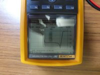
Diagnosing the problem has led me to identify a voltage spike at startup that occurs only when the power supply caps are empty or very nearly empty. If there is a small amount of energy left in these caps the voltage spike does not occur. Please see the attachment. This voltage spike does not happen on the surviving channel under any circumstances so far.
The speaker protection circuit did not like this kind of supply voltage and eventually decided that a capacitor needed to be distributed across as many nearby components as possible...who know so much 'stuff' fitted inside such a tiny can?
Are you able to think of a cause for the startup voltage spike on this one side? The power supplies are very simple and both seem to be outputting the very similar voltages apart from those moments from a cold start. I am thinking there may be something on the amplifier module that is causing this to happen, but my knowledge how of the circuit work is not good.
Anthony
Following on from earlier, I have released some magic smoke, but only from the speaker protection on one side..no amplifier modules were injured.
Diagnosing the problem has led me to identify a voltage spike at startup that occurs only when the power supply caps are empty or very nearly empty. If there is a small amount of energy left in these caps the voltage spike does not occur. Please see the attachment. This voltage spike does not happen on the surviving channel under any circumstances so far.
The speaker protection circuit did not like this kind of supply voltage and eventually decided that a capacitor needed to be distributed across as many nearby components as possible...who know so much 'stuff' fitted inside such a tiny can?
Are you able to think of a cause for the startup voltage spike on this one side? The power supplies are very simple and both seem to be outputting the very similar voltages apart from those moments from a cold start. I am thinking there may be something on the amplifier module that is causing this to happen, but my knowledge how of the circuit work is not good.
Anthony
Attachments
Hi Anthony
Not sure I fully understand your second paragraph and the curve you have provided....
Normally the big PSU caps are meant to be fully discharged after a while with the discharge resistor. There is nothing on the amplifier board that can cause what you describe. However, the only thing that I can think of is maybe if one (or both) 4700uf electrolytic cap has been damaged while you had problem previously with your speaker protection... as a test you can remove both caps from the board since the amplifier would be functional anyway.
Good luck
Fab
Last edited:
Hi Fab,
The curve/photo is the voltage going to the speaker protection board from a cold startup. So starts at zero volts, I turn on the amp, quickly hits 45 volts, falls back to 31 volts. Then I let it run for a short while and turn it off so the voltage falls back to zero.
The good channel just rises to 31V with no overshoot. Power supply is 400VA twin 20V secondaries and a simple CRC filter.
I'll check the 4700uf caps now.
Anthony
Do you run the speaker protection boards from secondary supply or from the main amplifier PSU?
I would suspect more the speaker protection board than the amplifier pcb...
Do not connect speaker, remove the speaker protection and observe the PSU voltage.
Fab
I would suspect more the speaker protection board than the amplifier pcb...
Do not connect speaker, remove the speaker protection and observe the PSU voltage.
Fab
- Home
- Amplifiers
- Solid State
- USSA-5 Build with Review