Thank you for the detailed information on how to get those holes drilled. My friend who is a mechanic also recommended this transfer punch set. It works really well, before those I had a lot of trouble getting the correct location for the holes for PCB mounting.BEFORE soldering on the MOSFET's ,
The board should be mounted on the heat sink , with the MOSFET's in place , on the thermal pads .
Soldering on MOSFET's is the last step .
Mounting the board
For some reason 3 x 0.5 mm machine screws have become a standard - with 50.8 tpi - which I think is too fine .
Consider using 4-40 machine screws instead .
I used 6mm long stand offs
Harwin 4-40 UNC x 6mm R44 - 1000602
But with probably need to use longer stand offs ... depending on the thickness of the thermal pads .
Make sure the board is mounted , centered on the heat sink , with the disconnects at the bottom .
If you gently clamp the heat sink on a drill press , drill the holes , keep it in place , then put the tap in the drill chuck .
Automatically the tap is lined up with the hole . Twist the chuck by hand to tap .
For a cutting fluid , synthetic motor oil seems to work fine .
Bend the leads of the MOSFET's around a form ... such as a drill bit ... maybe a 1/4" drill bit or smaller .
Before Soldering - there should be good surface contact between the MOSFET's , thermal pads and heat sinks .
6-32 machine screws will work with with Exicon MOSFET's , but there is no tolerance for error .
.
https://www.harborfreight.com/search?q=transfer punch
Yes, I got myself one of those digital oscilloscope with a tone generator. Still learning how to use it. I am planning to continue this hobby in my upcoming retirement , i need to keep my mind busy.

Where can I get boards for this amp?
I cannot find the schematic with all the components values.
thanks
I cannot find the schematic with all the components values.
thanks
Last edited:
Yes, I got myself one of those digital oscilloscope with a tone generator. Still learning how to use it. I am planning to continue this hobby in my upcoming retirement , i need to keep my mind busy.
Excellent . A generator and scope are needed to test audio amps . You need to see the waveforms to know if the amp is working correctly .
Suppose you are about to drill the holes for the 4 binding posts , or the holes for the USSA board on the heat sink .
If you set up a fence on a drill press , then automatically the distance between the fence and all the holes will be the same.
Make sure no dust gets caught between the fence and the metal - just the slightest bit of dust will throw the distance off .
A twist drill bit is really 2 chisels spinning around . The part in the middle that doesn't cut is called the web .
Suppose you are drilling larger holes for the binding posts .
Since the web doesn't cut , drill a pilot hole the diameter of the web first , then use the larger twist bit .
Keep the setting for the fence the same for the pilot holes and the larger drill bit .
I just got the thermal pads in place for the USSA 3.2 . With +/- 23 Vdc voltage rails , biased at 1.2 Amps
the heat sink gets uncomfortable to hold . So for your case design , recommend your heat sinks are raised up about 10 mm
so that there adequate ventilation underneath them .
Also , as Anatech pointed out , recommend your case has ventilation holes in the bottom and top so that the case
does not become an easy bake oven inside .
.
Last edited:
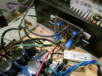
So here is the USSA 3.2 with AL2O3 thermal pads installed .
Instead of risking resoldering the MOSFET's , the length of the stand offs was increased
by the thickness of the thermal pads .
Searching for parts can be a pain .
So here are the part numbers if anyone needs them
Original Stand offs were 6mm ( 0.238" ) long
Harwin 4-40 UNC x 6 mm R44-1000602
Replaced with 8mm ( 0.314" ) stand offs ID 3.2mm no threads
Wurth WA-SBRrO 963080042
Aavid 4180G thermal pads 23.4 x 18.8 mm
thickness = 0.080" ( measured )
thermal conductivity = 79 W ( m x k )
Thermal paste was used
Thanks to everyone for providing their guidance on this issue .
I now have working Right Channel USSA 3.2 which sounds amazing .
Attachments
I am still gathering parts, waiting for the slow delivery of chassis from China, I choose a different one than I showed the link before, once I get it I will post the information.,
For the quick disconnect tabs listed in the BOM I think this is the correct mating female,
https://www.mouser.com/ProductDetail/571-7-160433-8
Is this the correct one?
Going back to the power supply, NOOB question, if i understand correctly the USSA-5 is feed by +VDC GND -VDC, not +VDC -VDC, correct?
Hunting for bits can be a pain , so I was just about to post a list to add to FAB's BOM .
IEC Case Connector - Connector only , no switch or fuse holder
Schurter 6100.3100
DPST Toggle Power Switch , with machine screws
Home Depot 125 Vac , 20 Amp
I'd prefer quick disconnects , but for some unknown reason these are difficult to find
AC Cable for inside the case - consider Belden 19364
has a foil shield with a drain wire
Feet - Home Depot EverBilt
Anti Skid Pads 1000 403 441
96450
Male disconnects for the USSA boards
TE Connectivity 170267-1
TAB 0.250 x 0.031 "
It may be best that this is the first part or component installed on the boards .
Tape the inside the jaws of lineman's pliers with electrical tape , to stop the jaws from scratching the disconnects.
Gently rocker them in
Female Disconnects - Auto Parts Stores
Here in Canada - box of 50 from Canadian Tire $15 Cdn
430 R 3 Watt feedback resistors
metal film - copper alloy leads - but if it makes any difference a magnetic sticks to the body
Vishay PR03000204300JAC00
3W Panasonic Metal Oxide power resistors are very popular on this site
but these Vishay metal film series are very reasonably priced
For a Coupling Cap , people have used everything from a WIMA box , to an ultra high end copper foil cap .
IMO most coupling caps can be improved by adding a by pass cap .
Suggest either a 10nF Cornell Dubilier Orange Drop 716p
or a surplus 8.2 nF Russian silver mica
.
Again , for the 1/4" female disconnects , suggest checking an auto parts vendor .
Highly recommend buying one's that have a sleeve .
The blue sleeve means its designed for 16 to 14 awg . The yellow sleeve indicates its designed for 12 to 10 awg .
For the distance between the disconnects on the USSA 5.0 rev 0.4 board , I'm measuring 0.274" ( 6.95 mm ).
One issue I ran into is that some of the yellow sleeves can have a diameter greater than 0.274 "
So if these are used , it looks like a bunch of crowded teeth .
For this reason , for the + Ve and - Ve , I had to switch from some fancy 10 awg cable ,
to Home Depot 14 awg stranded wire .
For the female disconnects , highly recommend buying a crimping tool.
Home Depot - GB Gardner - notice the crimping section by the handle .
https://www.homedepot.com/p/Gardner...ss-Armor-Edge-Wire-Stripper-GESP-70/300349444
Crimping is done with the sleeve in place .
After crimping on the disconnects , recommend soldering them .
Also , the diameter of some hole sizes get a bit strange , such as for some RCA jacks and the toggle switch .
Recommend buying a tapered - reamer .
https://www.princessauto.com/en/t-handle-tapered-reamer/product/PA0002910254
Drill the hole under size , then use the taper - reamer to bring the hole to have a tight tolerance .
.
Going back to the power supply, NOOB question, if i understand correctly the USSA-5 is feed by +VDC GND -VDC, not +VDC -VDC, correct?
If your case is metal , then it must be connected to Hydro Earth .
This Rod Elliot Article has become a reference article on the subject - suggest getting a print out of it .
https://sound-au.com/earthing.htm
Then typically most preamps and amp have their own analog ground node .
Hydro Earth and Analog Ground then have various components connected between them - as shown in Figure 5 .
The idea is that the RCA shield , power supply , amp board and speaker terminals are all referenced to the same Analog Ground Node .
In other words , everything is referenced to the same " 0 " Vdc .
Some people argue its an amplifier , so the Ground Node should be on the Amp .
On his F5 , Nelson Pass put the Ground node in the middle of everything .
But people who are used to working on a bench , typically use the power supply as the reference point for the ground .
I asked FAB about the Grounding of the USSA 5.0 boards .
The discussion on this begins on Post 2,011 .
Note there are 2 ground connections required for the USSA 5.0 rev 0.4 board .
Hopefully , I have this correct .
PGND - is the higher current analog ground for the MOSFET's
where as GND is the lower current analog ground for voltage gain section ( small signal transistors ) .
.
I am not sure about the terminology, I think what I wanted to say, do i need a differential power supply +VDC 0V -VDC or just simple power supply +VDC and -VDC.
Where can I get boards for this amp?
I cannot find the schematic with all the components values.
thanks
IMO the starting point for FAB's USSA Amp's is to make sure you can get the transistors .
If you can't find a source for 2sk2013 and 2sj313 's
then consider building the USSA 3.2 which uses Fairchild FQP3n30's and FQP3p20's .
These have also been discontinued , but will be much easier to track down .
The 2sk170 and 2sj74 BL can be sourced from DIYAudio Stores .
Order the BL's with the lower Idss ( 6 to 8 mA ) .
Both the USSA 3.2 and the USSA 5 can be built on the same USSA 5.0 rev 0.4 boards .
.
I am not sure about the terminology, I think what I wanted to say, do i need a differential power supply +VDC 0V -VDC or just simple power supply +VDC and -VDC.
The power supply needs to provide + 24 Vdc , Analog Gnd , and - 24Vdc .
Analog Gnd is 0 Vdc
Suggest reading my post above #2,129
In the case of FAB's amps , I've drawn a picture of how the Analog Gnd should be connected in Post #2,014
However , recommend you build 2 power supplies , one for each channel .
.
Last edited:
I apologize, I had to read this several times to understand the ground concept, after your second message on this I finally got it.If your case is metal , then it must be connected to Hydro Earth .
This Rod Elliot Article has become a reference article on the subject - suggest getting a print out of it .
https://sound-au.com/earthing.htm
Then typically most preamps and amp have their own analog ground node .
Hydro Earth and Analog Ground then have various components connected between them - as shown in Figure 5 .
The idea is that the RCA shield , power supply , amp board and speaker terminals are all referenced to the same Analog Ground Node .
In other words , everything is referenced to the same " 0 " Vdc .
Some people argue its an amplifier , so the Ground Node should be on the Amp .
On his F5 , Nelson Pass put the Ground node in the middle of everything .
But people who are used to working on a bench , typically use the power supply as the reference point for the ground .
I asked FAB about the Grounding of the USSA 5.0 boards .
The discussion on this begins on Post 2,011 .
Note there are 2 ground connections required for the USSA 5.0 rev 0.4 board .
Hopefully , I have this correct .
PGND - is the higher current analog ground for the MOSFET's
where as GND is the lower current analog ground for voltage gain section ( small signal transistors ) .
.
Eliad ,
Learning the Terminology and approaching technical issues using methodical approach takes a while to learn .
On a Preamp or Amp , the analog Ground Node is a connection point where everything is referenced to the same " 0 Vdc . "
Its often called Star Grounding because the RCA Ground , Speaker Ground , Amp Ground and Power Supply Ground
are all directly connected to that same point .
On FAB's USSA Amps , he recommends that the Analog Ground is physically located on the Ground of the power supply board.
But the RCA Ground goes straight to the USSA Board .
IMO Hydro Earth is quite noisy . So its not recommended that its connected to Analog Ground .
Code requires that a metal case is connected to Hydro Earth as shown in the Rod Elliot article .
Then Analog Ground and Hydro Earth have components connected between them .
The chassis of many scopes is connected to Hydro Earth .
So the second that a scope probe is connected to Analog Ground of an amp , it adds noise to the Analog Ground .
This is the classic situation of disturbing the very thing that you are trying to measure .
.
At the risk of repeating a previous statement ,
for the USSA 5.0 rev 0.4 board , I'm measuring distance of 0.274 " ( 6.95 mm ) between the disconnects .
Female disconnects designed for 10awg to 12awg have a yellow sleeve .
Some yellow sleeves have a diameter of less than 0.274 " ( 6.95 mm ) so they will fit fine .
I just bought a box of 50 from Canadian Tire and the yellow sleeve on these measures 0.330 " ( 8.4 mm )
So these will create a bunch of crowded teeth .
.
It is only the PGND connection where I recommend 12AWG, the rest can be 14AWG. Only one female disconnect should be easier to fit the yellow sleeve. Alternatively, you can remove the yellow sleeve and use heat shrink to replace the sleeve if it is easier for the PGND.
Fab
Fab
If anybody is looking for the obsolete Darlington driver pairs needed for USSA 5.1a or b,
I got these, they look genuine as far as I can tell. I have one of those testers and they show up as Darlington and provides some measurements. I can post the measurements later if interested.
https://www.ebay.com/itm/276437288108
I got these, they look genuine as far as I can tell. I have one of those testers and they show up as Darlington and provides some measurements. I can post the measurements later if interested.
https://www.ebay.com/itm/276437288108
Measurements for the batch I have, they are close values, these are typical measurements.
2SD2081 hFe 31, Vbe 1.23V, Ic 6mA
2SB1259 hFe 36, Vbe 1.31V, Ic 6.1mA
2SD2081 hFe 31, Vbe 1.23V, Ic 6mA
2SB1259 hFe 36, Vbe 1.31V, Ic 6.1mA
Hfe of a darlington medium power device should be taken at much higher IC current. IC of 6ma does not say much. Their hfe curve varies a lot with current and can go more than 1000 at about 1A. In this application IC is close to 100ma range. hfe measures should be taken at different IC values to compare with datasheet provided curve to determine if genuine or at least at the intended used current.
Fab
Fab
- Home
- Amplifiers
- Solid State
- USSA-5 Build with Review