Eliad,
Have you ordered the power supply components yet ?
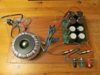
Here is the test power supply I used for 1 channel of the USSA 3.2 Amp, .... and it sounded fabulous .
Transformer AnTek AN-4218 300VA with dual 18 Vac + 18 Vac secondaries
The caps are 4 x 15,000uF and 4 x 10,000uF
2 Amp Slow Blow Fuse on the input , 3 Amp fast blow fuses on the +Ve and -Ve output .
Resistors are 0R11 on the +Ve and -Ve ( 0R33 // 0R33 // 0R33 )
Long story short , go with a dual power supply .
If you try to cut corners with the power supply , it will limit the ability of the USSA amps .
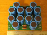
Power supply caps are quite expensive , but consider 2 power supply boards as shown on the right .
With 12 x 10,000uF 50 Vdc caps on each board .
Sit down before seeing the price , but these provide a high performance / cost ratio .
So a Qty 24 of these caps will be needed ( to point out , lead distance of 10mm is standard for caps with snap in leads )
Vishay MAL225641103E3
https://www.vishay.com/docs/28410/256pmg-si.pdf
Have you ordered the power supply components yet ?
Here is the test power supply I used for 1 channel of the USSA 3.2 Amp, .... and it sounded fabulous .
Transformer AnTek AN-4218 300VA with dual 18 Vac + 18 Vac secondaries
The caps are 4 x 15,000uF and 4 x 10,000uF
2 Amp Slow Blow Fuse on the input , 3 Amp fast blow fuses on the +Ve and -Ve output .
Resistors are 0R11 on the +Ve and -Ve ( 0R33 // 0R33 // 0R33 )
Long story short , go with a dual power supply .
If you try to cut corners with the power supply , it will limit the ability of the USSA amps .
Power supply caps are quite expensive , but consider 2 power supply boards as shown on the right .
With 12 x 10,000uF 50 Vdc caps on each board .
Sit down before seeing the price , but these provide a high performance / cost ratio .
So a Qty 24 of these caps will be needed ( to point out , lead distance of 10mm is standard for caps with snap in leads )
Vishay MAL225641103E3
https://www.vishay.com/docs/28410/256pmg-si.pdf
Attachments
Last edited:
Eliad ,
Actually , if you look inside FAB's Galion TS A20 Amp , you 'll see he's used dual supply with 4 x 47,000uF caps , 35 Vdc 85oC per channel .
https://www.cde.com/resources/catalogs/380-382.pdf
So with 8 caps , that's a total of 376,000 uF .
Enough charge to start my Honda CR-V .
.
Actually , if you look inside FAB's Galion TS A20 Amp , you 'll see he's used dual supply with 4 x 47,000uF caps , 35 Vdc 85oC per channel .
https://www.cde.com/resources/catalogs/380-382.pdf
So with 8 caps , that's a total of 376,000 uF .
Enough charge to start my Honda CR-V .
.
Yes, I am going with dual power supply, I learned long time ago, if I go cheap I will pay way more later.
I have concerns about the space in the chassis I ordered and I went with @prasi LT4320 CRC power supply board, this one has 4 x22000 capacitors per board. I also have @prasi CRCRC power supply board but I think this wont fit in the chassis. My chassis is hopefully showing up in a week or 2. Very slow shipping from China, once I have it I will post information, the price is good, maybe too good, we will see. I didnt order the chassis I posted earlier, that was way to good to be true.
I also got 2 slow start and the speakers protection from diyaudiostore. I plan to use the same Antec toroidal, I have one but is AU version, I believe AS version is very close in size. I will test with the AU version and if I am satisfied with 18V then I will order the AS version which is supposed to be made for audio.

Yes, I am going with dual power supply, I learned long time ago, if I go cheap I will pay way more later.
I have concerns about the space in the chassis I ordered and I went with @prasi LT4320 CRC power supply board, this one has 4 x22000 capacitors per board.
Fantastic . Squeezing everything into a case can be quite a challenge .
Because of the topology used with the USSA Amps ,
and your transformers are 2 x 300 VA ( or less ) , I don't really think a soft start is required .
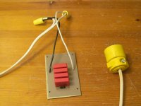
However , as I was sternly told years ago , both the hot and neutral must be switched . Hence the need for a DPST power switch .
Then connect a 10nF class X rated cap across the hot terminals to stop arching between the contacts when the amp is switched on .
What I highly recommend is building a DIY EMI filter designed for audio
which I connected after the power switch .
When listening to a Mozart Piano Concerto , and using a CRC power supply board ,
when this bank of 4 x 0.47uF class X2 caps is plugged in ,
I can hear a slight reduction in the distortion during the transient response of the piano
and a slight improvement in clarity in the string section .
https://www.wima.de/en/our-product-range/rfi-capacitors/mkp-x2/
The EMI filter also needs a common mode choke - not shown .
I have concerns about the space in the chassis I ordered and I went with @prasi LT4320 CRC power supply board, this one has 4 x22000 capacitors per board.
Fantastic . Squeezing everything into a case can be quite a challenge .
Because of the topology used with the USSA Amps ,
and your transformers are 2 x 300 VA ( or less ) , I don't really think a soft start is required .
However , as I was sternly told years ago , both the hot and neutral must be switched . Hence the need for a DPST power switch .
Then connect a 10nF class X rated cap across the hot terminals to stop arching between the contacts when the amp is switched on .
What I highly recommend is building a DIY EMI filter designed for audio
which I connected after the power switch .
When listening to a Mozart Piano Concerto , and using a CRC power supply board ,
when this bank of 4 x 0.47uF class X2 caps is plugged in ,
I can hear a slight reduction in the distortion during the transient response of the piano
and a slight improvement in clarity in the string section .
https://www.wima.de/en/our-product-range/rfi-capacitors/mkp-x2/
The EMI filter also needs a common mode choke - not shown .
Attachments
I highly recommend not to unless your lights blink even though you shut those down. And your neightbour AC makes tractor noises.What I highly recommend is building a DIY EMI filter designed for audio
" I highly recommend not to unless your lights blink even though you shut those down. And your neightbour AC makes tractor noises."
Here in Ottawa , its worse than a neighbour's A/C making tractor noises . Ottawa is run by developers
so the out of control suburban sprawl has put quite a strain on our city's hydro grid . The LED's lights in our 1950's house flicker all the time .
Put it this way , I have a car battery for back up , when the power goes out , so I can still have WiFi .
Also , in the EU , hydro is 230 Vac , where as its approx 115 Vac here .
The Fo Felix EMI filter is highly regarded
Note that with this design , there isn't a cap connected between the hot and earth , and neutral and earth .
Also , want to make sure the common mode choke is large enough to handle the current .
Hey everybody!
So over the years people have asked about the old version, made by someone else.
It's probably time for an updated one. This one is a bit different. You may notice it does not have following capacitors after the choke. I have tried both ways, and my preference is strongly without the following X2 capacitors. Also the capacitors prior to the choke are not varied in size because overall capacitance is more important - and they won't randomly resonate with each other.
The other major change is the addition of bypass resistors for the chokes. These don't ruin the...
- Destroyer OS
- Replies: 220
- Forum: Group Buys
For a CLrRC power supply , in post #2,016 , I've shown the algebra how to calculate the dampening resistors .
Looking from the supply rails into the Amp , the supply rails see a CCS - which has a very high impedance .
So the Amp itself does not provide any dampening for the chokes .
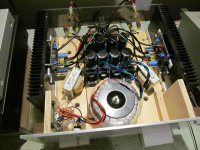
For the mono power supply shown below , with 8 x 22,000uF caps , I tried
1) 2.5 mH chokes + 0R25 dampening resistors . After another 60 hours of break in , one channel sounded great .
But then when both the R and L channels were connected , the sonics were awful .
2 ) So took out the 2.5mH + 0R25 's , and replaced them with 0R1 12 Watt resistors .
After 10 hours of break in , both channels with the CRC power supply sounded great .
So I knew the 8 x 22,000 uF caps could store enough charge and the ESR was low enough .
3 ) Then took out the 0R1 resistors and connected the 2.5mH chokes , without the dampening resistors
and the sonics were slightly more refined than with the 0R1 resistors .
fo = 1 / ( 2 * Pi * sqrt ( L * C2 )) , so with a 2.5mH choke and C2 = 2 x 22,000uF
that works out to be 15.2 Hz .
fo is so low , in my opinion , leave the dampening resistors out .
The USSA 3.2 sounds so amazing now , I don't even want to tinker with the power supply any more .
I'm going to cut a piece of polycarbonate for the top and that's it .
.
Looking from the supply rails into the Amp , the supply rails see a CCS - which has a very high impedance .
So the Amp itself does not provide any dampening for the chokes .
For the mono power supply shown below , with 8 x 22,000uF caps , I tried
1) 2.5 mH chokes + 0R25 dampening resistors . After another 60 hours of break in , one channel sounded great .
But then when both the R and L channels were connected , the sonics were awful .
2 ) So took out the 2.5mH + 0R25 's , and replaced them with 0R1 12 Watt resistors .
After 10 hours of break in , both channels with the CRC power supply sounded great .
So I knew the 8 x 22,000 uF caps could store enough charge and the ESR was low enough .
3 ) Then took out the 0R1 resistors and connected the 2.5mH chokes , without the dampening resistors
and the sonics were slightly more refined than with the 0R1 resistors .
fo = 1 / ( 2 * Pi * sqrt ( L * C2 )) , so with a 2.5mH choke and C2 = 2 x 22,000uF
that works out to be 15.2 Hz .
fo is so low , in my opinion , leave the dampening resistors out .
The USSA 3.2 sounds so amazing now , I don't even want to tinker with the power supply any more .
I'm going to cut a piece of polycarbonate for the top and that's it .
.
Attachments
Indeed, CRC with R =0R25 is already a bit too high. 0R20 ( as per manual) is the max compromised value ( between speed and noise) for a CRC (and without L) I would say to get better transient attack…it is also related to C value….
With a CLC, the L has already an R value imbedded so an additional R may be removed or at least the value reduced.
In short, there is no specific right or wrong value but a compromise to get the characteristics you want….so like Underhill try experimenting because overall sound result is also function of the amplifiers characteristics…..Underhill, Can you specify your choke DC resistance….
L is probably better but takes more space in the chassis and increases the overall price too…
Fab
Last edited:
Great achievement, cheers!
Thanks to FAB , Project16 , Vunce , Anatech and everyone else who provided the USSA Amp design and Guidance when I needed it .
.
Underhill, Can you specify your choke DC resistance….
L is probably better but takes more space in the chassis and increases the overall price too…
FAB ,
These are Hammond 159ZL chokes , where L = 2.5mH and r = 0.044 ohms
I showed the algebra for the transfer function in post # 2,016
Rdamp = 2 x Zeta x sqrt ( L / C2 )
If I recall correctly , Zeta = 0.707 in an ideally dampened system
... and the equation shows the second bank of caps helps with the dampening
I bought the 4 x 22,000uF Mundorf caps about 12 years ago , so that's what I used in the 2nd bank of caps .
The datasheet says ESR is in the order of 0.009 for these .
So if C2 = 2 x 22,000uF , then Rdamp = 0.33 - 0.044 ..... so the math says to connect a dampening resistor of 0R29
fo = 15.2 Hz
But listening to a Mozart Piano Concerto , I decided to leave the dampening resistors out .
but if C2 is increased to 2 x 47,000uF , Rdamp = 0.23 - 0.044 ... so connect a dampening resistor of 0R19
and fo drops down to 10.4 Hz
.
Last edited:
FAB ,
To point out , originally I was going to build a Zenquito Amp because I had the 2sk246 BL and 2sj103 BL jFET's .
But decided to build your FSSA Amp , but then thought I was taking on too much .
I have zero chance of finding 2sk2013 and 2sj313's , so I decided to build the USSA 3.2 .
The DIYAudio Stores V3 power supply was already well on the way with 8 x 22,000uF caps .
With a 600VA transformer that's a slightly bigger supply than what's in an Aleph J .
From what I can figure out , when listening to music , the timbre of the instruments sounds more natural and un forced
with a bigger power supply . The music also sounds more forward with a bigger supply .
Using Home Depot 14awg stranded wire for the power wiring , I measured a voltage drop of 4.5mVdc @ 1.2 Amps for a 25 cm length .
Giving R = 3.5 mOhms , which doesn't sound like much ,
but then the ESR of each cap is in the neighbourhood of 9 to 22 mOhms .
So I took out the Home Depot special and replaced it with some 12 awg fancy wiring - which I had .
The voltage drop for this cable was nearly 1/2 .
.
I have zero chance of finding 2sk2013 and 2sj313's , so I decided to build the USSA 3.2 .
You can get them here
For Sale Thread 'Toshiba 2SK2013/2SJ313'
I have some 2sk2013/2sj313 for sale.
Matched Pair
Matched Quartet
Matched Octet
Shipping with tracking number 15usd
(10usd without tracking)
Matched Pair
Matched Quartet
Matched Octet
Shipping with tracking number 15usd
(10usd without tracking)
Brijac , this leads to a question that I wanted to ask FAB .
What is the difference between a transistor design for audio and a general purpose switching transistor ?
Linearity seems to be one key . For example , a lateral MOSFET like a 2sk2013 has good linearity .
Looking at the graphs on the datasheet di / dVgs has a good linear operating region - its close to a straight line .
https://ksp-electronics.com/media/69649/2sk2013.pdf
Note how the family of curves for the 2sk2013 is pretty good . While the Fairchild 's FQP3n30 family of curves is all wonky .
https://www.onsemi.com/pdf/datasheet/fqp3n30-d.pdf
The other issue is Noise Figure .
Looking at the datasheets , notice how transistors design for audio usually have the Noise Figure stated .
https://www.audiolabga.com/pdf/2SK170.pdf
.
Last edited:
Boards arrived, thanks Fab 🙂 One build with 2sk2013/2sj313 coming soon 😊

Should it help, I have a pair of boards for sale on the forum.
Stuffed for USSA3, but could be changed easily...
Stuffed for USSA3, but could be changed easily...
In general you want very good linearity of transfer characteristics. 2sk2013/2sj313 are literally demonstration of force 😅 Audio made ones are made with that in mind, while general ones (which can be quite good) are for a lot of different uses (i recently designed pump controller for race car tuner shop that must be able to withstand 55A in bursts).What is the difference between a transistor design for audio and a general purpose switching transistor ?
Last edited:
" i recently designed pump controller for race car tuner shop that must be able to withstand 55A in bursts "
We used to race 1hp electric vehicles with 2 x 12Vdc wheel chair batteries .So currents were in the order of 32 Amps and even higher .
For a PWM ( Pulse Width Modulation ) controller , consider using a single IXFN180n10 , which has a maximum Rds(on) = 8mOhms .
.
We used to race 1hp electric vehicles with 2 x 12Vdc wheel chair batteries .So currents were in the order of 32 Amps and even higher .
For a PWM ( Pulse Width Modulation ) controller , consider using a single IXFN180n10 , which has a maximum Rds(on) = 8mOhms .
.
" In general you want very good linearity of transfer characteristics. 2sk2013/2sj313 are literally demonstration of force 😅 Audio made ones are made with that in mind, while general ones (which can be quite good) are for a lot of different uses "
Brijac , Thanks for confirming this . Looking at the Id vs Vgs curve for a 2sk2013 , there is a very linear operating region - its almost a straight line .
.
Also , years ago I took out a 2n3906 and replaced it with a 2n5401 and the amp sounded miles better .
I thought the difference was the Noise Figure . But I see the Noise Figure is stated for both transistors .
https://www.onsemi.com/pdf/datasheet/2n3906-d.pdf
https://www.onsemi.com/pdf/datasheet/2n5401-d.pdf
But I do recall Nelson Pass saying to use 2sk170's in a phono stage , because j113 (?) were too noisy .
.
- Home
- Amplifiers
- Solid State
- USSA-5 Build with Review