first amp board connected to the power supply. I think I have a big problem. the meter connected at the output shows 25Vdc. In AC mode the meter shows just few mV. As far as i understand I should not have DC at the output. Also, P1 adjustment changes the mV reading at TP1 TP2, adjustment of the P2 does nothing to the reading either at TP1- TP2 or TP3-TP4.
Recommend disconnecting the Amp from the main power supply .
Make a set of disconnect cables so that your amp can be connected to your bench power supply .
Set your bench power supply to +10 Vdc and -10 Vdc turn it off , then connect the Amp to it .
At the Amp , make sure both the PGND and GND are connected to the bench power supply Ground .
Then set the bench supply to monitor the current .
Connect your generator and scope to the Amp .
Turn on the bench supply , and watch if the current suddenly jumps .
If it does there could be an issue .
If doesn't , then watch for a waveform on your scope .
Slowly bring up the trimmers on the amp , and voltage on the bench supply .
You'll see crossover distortion as the waveform changes from push to pull .
As you increase the current this distortion should start to disappear.
I adjusted the trimmers by measuring the voltage drop across the source resistors .
The Amp will run with a bias as low as 100 mA or 200 mA .
.
I think I probably burned out at least one of ECW20. I recall at one of the steps I connected my bench supply with the polarity in reverse. I desoldered all the transistors and checked them except ECW20 pair. I will desolder those and check them too. Anything else that I should check? I have one of those component testers which i used to test the transistors i desoldered.
Well, lesson learned, check and check and check again and dont do this work when I am tired and my mind is not focused. Another dumb mistake.
The other card works as it should. I can adjust the P1 and P2 for the speaker output of less than 1mVdc and at the TP1-TP2 i can get around 60mV, if I read correctly the instruction this is how the bias should be set. My bench power supply shows 1.3A at 25Vdc
Good news, the Exicon ECW20 pair tested ok. Maybe one of the electrolytic capacitors is busted. I will continue to investigate what i did. I continue to kick myself for this dumb mistake.
Eliad ,
Test each section of the Amp 1 stage at a time . Don't use the prayer technique - That's when the entire Amp is connected
and you pray that it works .
As such , I highly recommend testing the USSA Amp using a bench power supply without the Exicon MOSFET's .
Again , set the bench supply to + 10 Vdc and - 10 Vdc .
Connect the generator and scope .
Slowly bring up the trimmers and watch for a wave form on the scope .
Obtain the bias current for the 2sk2013 and 2sj313's by measuring the voltage drop across the source resistors .
It should be in the ball park of 25 mA .
Check Prasi's power supply boards to make sure they are OK - with a 3K3 1 W load resistor .
They are going to need to powered up for at least 50 hours before the Amp sounds great .
So keep these switched on for 2 days .
.
@Uunderhill , thank you for the advice. I build the boards one step at a time and tested them but one of the boards i connected the power wrong way during one of the later test stage. It looks I damaged 3 out of 4 of the electrolytics on that board. I already checked the transistors, I will check the diodes too. Fortunately I have a working board and I can compare the damaged board to the working board. In the meantime I will keep Prasi CRC board powered up to condition those large capacitors. These boards already have a 3k3 1W bleeding resistor at the output. I guess this could count for a load, if I am not mistaken.
It looks I damaged 3 out of 4 of the electrolytics on that board.
Someone correct me if necessary , but the fact that +24 Vdc was measured on the the output suggests that the
caps for the +Ve rail were not shorted out .
Run Prasi's cap board, with load resistors only , to verify they are OK .
Complete testing the Amp using the bench power supply .
This will help you get used to the trimmers .
Also , recommend taping the jeweler's screw driver , so that if its dropped , it won't short anything out .
When you connect Prasi's power supply boards , to the tested Amp ,
I still highly recommend connecting 3 Amp fast Blow fuses between the +Ve and the Amp , and the -Ve and the Amp .
Connecting these fuses has saved my tail feathers on 3 separate occasions .
Automotive parts stores have those inline fuse holders .
.
i tested the damaged board on the bench power supply and I got the same result as when I connected Prasi power supply, The capacitors I found damaged were tested with an LCR meter, they are definitely damaged. I am placing an order for replacement. I will get those inline fuse holder and use the fast blow fuses in them.
EXICON power transistors and the MOSFET drivers test ok with this little device I have. Hopefully is not misleading me to think those transistors are ok.
https://www.amazon.com/Transistor-Capacitor-Resistor-Capacitance-Automatic/dp/B08R9NPZRZ?th=1
EXICON power transistors and the MOSFET drivers test ok with this little device I have. Hopefully is not misleading me to think those transistors are ok.
https://www.amazon.com/Transistor-Capacitor-Resistor-Capacitance-Automatic/dp/B08R9NPZRZ?th=1

Eliad
If you believe that only the caps are damaged and want to to be re-assured for the rest you can omit for testing the big power supply caps on the board and replace temporarily the 2 feedback caps by any other one you have in stock and retest with a bench power supply. Remove the output transistors and re-start testing from the manual. Just a suggestion.
Fab
Good news I got the board running again. The hard to find MOSFET and output transistors were ok.
I had a spare PCB and i fixed the hard way. I removed all the parts from the broken PCB, i checked all the parts and rebuild the new PCB from ground zero. I replaced all 4 electrolytic capacitors, the small diodes checked ok but I replaced them anyhow, J112 checked ok but since I had some extra I replaced them. I got everything working up to the bias adjustment with no load. Now the output reads 0.1mV. I run out of the thermal paste, I am waiting for a shipment from ebay, should be here soon.
Lesson learned, dont do any power testing if I dont have full attention and triple check connections before applying power.
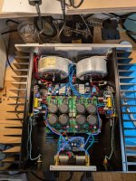
Final stages for testing. Bias is set at 60mV, the heatsinks are huge, they get warm but lower than 50C. I was curious about the weight of this thing, it is 46 pounds (20.8Kg). Huge indeed. Good exercise equipment.
I did the testing with 8R load and I also tested for sound with a crappy speakers I have for testing. All good. Now testing for output impedance and damping factor.
If anyone interested in the chassis, I can provide the ebay link and any measurements you want to know.

I did the testing with 8R load and I also tested for sound with a crappy speakers I have for testing. All good. Now testing for output impedance and damping factor.
If anyone interested in the chassis, I can provide the ebay link and any measurements you want to know.
Congratulations for you nice build Eliad.
Yes damping factor value a bit higher can be better but between 54 or 45 it is quite similar. Since only 1mV measurement difference makes a difference in the calculated value, there is a high tolerance on the DF value…
Yes 55C should be the highest temperature for the heatsink. Have you installed 60C thermal switch on the heatsinks to be more safe?
Fab
Yes i connected the thermal switch, the photo above was before I completely finished the amp. Now I have a thermal switch for each heatsink and the speaker protection module is now connected. The amp has been running feed from a DAC and on a 8R power resistor load for 12 hours, the temp of the heatsink is most of the time about 45C, sometimes if the room gets warmer gets to 47C. I plan to check readjust the bias once more after I do this initial burn in test. I will take some pictures of the final project. Soon I will give my impression for the sound.
Great Eliad. You can increase even a bit more the bias if you want. The sound character of the amp will continue to reveal itself even up to 100 hours or so…. I also suggest that you replace the input cap with something even better to get the full potential….
Fab
Fab
Last edited:
@fab USSA-5 has been continuously running for over 50 hours. Bias is now at 80mV, input voltage is 25Vdc. The temperature at the hottest 53C spot. I think I will leave it at this point. Now I have to do the listening test after few more hours of burn in. I did some spot listening and sounded quite good.
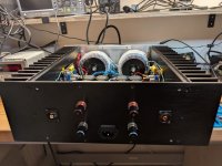
here are the pictures of my final build. I got 300VA 18V AntekInc transformers. Heatsinks are massive and do a great job cooling the output MOSFET.
I got this case from ebay, search for Power Amplifier Chassis Aluminum Class A DIY HiFi Pass A Case W430 H150 D418 mm 4315Pass. You might find the same chassis on aliexpress.
Another option for case would be Tokban 430*150*315/363/415mm All Aluminum Power Amplifier Chassis Enclosure Class A Amplifier Audio Case Shell Accessories, get the 400mm depth. This chassis heatsink are not as massive as the one above.
If anyone wants to know any measurements for either of these two let me know.
Attachments

First listening session using my Klipsch Belle clone speakers. Input RPT3 line preamp. It sounds quite good, analytical I would say. No hum.
I am comparing this to my Engineer Baby Huey tubes amp. Baby Huey is different sound for sure but also has hum which is a project that I need to figure out.
About USSA-5 what are the recommendations for the upgrade of the input capacitors?
I am comparing this to my Engineer Baby Huey tubes amp. Baby Huey is different sound for sure but also has hum which is a project that I need to figure out.
About USSA-5 what are the recommendations for the upgrade of the input capacitors?
Eliad ,
If your RPT3 preamp has a coupling cap on the output , a coupling cap on the input of the USSA 5 won't be needed .
As standard practice , recommend soldering a 1M resistor between the output of the coupling cap on the preamp
and the analog ground . Suggest using a metal film resistor for this .
However , if you are set on replacing the coupling cap on the input of the USSA Amp , because of the transfer function
and low end phase distortion , make sure its the value FAB recommended .
To answer your question , a few years ago I conducted a subjective listening test with a few audio caps
... and my subjective opinion is that I could hear a touch of harshness with the Mundorf Supreme and the original Audience AuriCap .
Where as I didn't hear any harshness with either of the Clarity Caps or the Audyn True Copper Cap .
The Audyn True Copper cap was the winner , but I don't think they are worth the money , and they are massive beasts .
In my opinion , the Clarity Cap CSR was the best cap with horrific 1980's DDD CD recordings .
Recommend by passing it with a 8.2nF Russian surplus silver mica cap , but these are quite large .
As a second choice for a by pass cap , a 10nF Orange Drop 716 series is very good .
Regardless of which cap you go with , make sure it will physically fit .
.
If your RPT3 preamp has a coupling cap on the output , a coupling cap on the input of the USSA 5 won't be needed .
As standard practice , recommend soldering a 1M resistor between the output of the coupling cap on the preamp
and the analog ground . Suggest using a metal film resistor for this .
However , if you are set on replacing the coupling cap on the input of the USSA Amp , because of the transfer function
and low end phase distortion , make sure its the value FAB recommended .
To answer your question , a few years ago I conducted a subjective listening test with a few audio caps
- Mundorf Supreme ( not any of the EVO series )
- original series Audience AuriCap
- Clarity Cap CSR series
- Clarity Cap CMR series
- and a very expensive Audyn True Copper Cap
... and my subjective opinion is that I could hear a touch of harshness with the Mundorf Supreme and the original Audience AuriCap .
Where as I didn't hear any harshness with either of the Clarity Caps or the Audyn True Copper Cap .
The Audyn True Copper cap was the winner , but I don't think they are worth the money , and they are massive beasts .
In my opinion , the Clarity Cap CSR was the best cap with horrific 1980's DDD CD recordings .
Recommend by passing it with a 8.2nF Russian surplus silver mica cap , but these are quite large .
As a second choice for a by pass cap , a 10nF Orange Drop 716 series is very good .
Regardless of which cap you go with , make sure it will physically fit .
.
Last edited:
- Home
- Amplifiers
- Solid State
- USSA-5 Build with Review