Revisiting the issue of the thermal pads
Berqguist SIL PAD TSP A300 .......... 25.4 x 19 x 0.44 mm ..................... 3.0 W / ( m x K )
Keratherm model 86 / 82 ............... 32 x 23 x 0.25 mm ......................... 6.5 W / ( m x K )
AL203 ................................................................................................. 25 to 79 W / ( m x K )
Knowing the co efficient for thermal conductivity for these different materials provides a good guide .
But the bottom line is what is the difference between the case temp of the ECW20 MOSFET's and the Heat Sink
when a thermal pad is placed between them ?
DIYAudio member MistyBlue conducted an extensive set of test measurements , for different thermal pads materials ,
and provided the write up . His updated test results are on Post #18
The bar graph near the bottom shows the test results , between the case temp and heat sink temp , for different materials .
Looking at his test results , the bottom line , as everyone advised me here , is to go with AL2O3 pads .
So I'll find a way to make these Aavid 4180G pads fit with a thickness of 2 mm .
https://www.mouser.ca/ProductDetail/Aavid/4180G?qs=2v7q0MSBcBMwt5GBytMENg==&srsltid=AfmBOor0-NciUe6dsCgKpxE4u_fvQMKBffhW8WP6QxwDBVcSfv5T7XsG
.
Berqguist SIL PAD TSP A300 .......... 25.4 x 19 x 0.44 mm ..................... 3.0 W / ( m x K )
Keratherm model 86 / 82 ............... 32 x 23 x 0.25 mm ......................... 6.5 W / ( m x K )
AL203 ................................................................................................. 25 to 79 W / ( m x K )
Knowing the co efficient for thermal conductivity for these different materials provides a good guide .
But the bottom line is what is the difference between the case temp of the ECW20 MOSFET's and the Heat Sink
when a thermal pad is placed between them ?
DIYAudio member MistyBlue conducted an extensive set of test measurements , for different thermal pads materials ,
and provided the write up . His updated test results are on Post #18
Edit 15/01/2025: I have an updated version of the Thermal Pad Tests pdf, which includes some extra stuff. See post 18.
Thought Id share the results from some tests I did recently after getting myself into trouble!
I hope it may be of some use.
Thought Id share the results from some tests I did recently after getting myself into trouble!
I hope it may be of some use.

The bar graph near the bottom shows the test results , between the case temp and heat sink temp , for different materials .
Looking at his test results , the bottom line , as everyone advised me here , is to go with AL2O3 pads .
So I'll find a way to make these Aavid 4180G pads fit with a thickness of 2 mm .
https://www.mouser.ca/ProductDetail/Aavid/4180G?qs=2v7q0MSBcBMwt5GBytMENg==&srsltid=AfmBOor0-NciUe6dsCgKpxE4u_fvQMKBffhW8WP6QxwDBVcSfv5T7XsG
.
Last edited:
Eliad ,
The issue of a case is a total PIA . You'll need to find one that has enough space to squeeze in the power supplies
and the heat sinks dissipate enough heat .
I started a discussion concerning heat sinks on Post #2018 , pg 101 .
But the bottom line is that each heat sink will need to dissipate 63 Watts = 2 x 24 Vdc x 1.3 Amps .
Say a room temp of 21oC . Probably want a operating temp of 50oC , because that's about the limit of what a person can hold .
That gives a heat sink with a rating of 0.46 oC / W = ( 50oC - 21oC ) / 63 Watts .
But downgrade the ability to dissipate heat by 25% . So look for a case with each heat sink rated at 0.35oC / W .
As I just discovered , the metal backs of the Exicon ECW20 MOSFET's is connected to the source .
As such , the MOSFET's will need to be mounted using pads that are electrical insulators , but thermally conductive .
See post above . Highly recommend reading MistyBlue's test results .
.
Eliad,
Yes, a Dissipante 4U 400mm case would fit a USSA-5 project with dual mono power supply and be more than adequate to handle the heat generated.
The Mini Dissipante doesn’t have enough internal space.
Good practice is to ALWAYS use isolation pads for devices attached to heatsinks.
Yes, a Dissipante 4U 400mm case would fit a USSA-5 project with dual mono power supply and be more than adequate to handle the heat generated.
The Mini Dissipante doesn’t have enough internal space.
Good practice is to ALWAYS use isolation pads for devices attached to heatsinks.
I saw your post with the Exicon adventure. I plan to get those AL oxide insulators from Aliexpress, I noted they have 0.6mm and 1mm, probably I will get the 1mm because I understand they are quite easy to break.
Maybe what I should do is to find some good heatsinks and build a chassis around those. Any suggestions for independent heatsinks source? I need heatsinks in order to test for sound.
Maybe what I should do is to find some good heatsinks and build a chassis around those. Any suggestions for independent heatsinks source? I need heatsinks in order to test for sound.
Eliad , a significant amount of effort goes into making a case .
As such , since you are in the States , I'd say buy a case from DIYAudio Stores .
However , if you are determined to fabricate a case , having access to metal shear and drill press is pretty well a must .
If you don't have access to a metal sheer , you could build a case from a hybrid of materials .
As discussed in Post #2018 , Newark sells these Multicomp heat sinks .
MP008442 is rated at 0.42oC / Watt
MP008443 is rated at 0.36oC / Watt
Or ask Vunce where he managed to find the heat sinks he used in his DIY case # 2043 .
Far Side Cartoon : " ... and Joe couldn't figure out why his Harley Davidson kept over heating . "
.
I am lucky on this front, a good friend of mine has all the tools and expertise to make an AL chassis around the heatsinks. For this reason I thought about this angle on how to deal with the chassis. I will gather the power supply boards and the transformers and have an idea what I need and go from there.
Eliad,
Indeed you are lucky that your friend can help you with putting together the chassis.
Still, have a look at the off the shelf options; the DIY chassis has multiple parts - the heat-sinks, base, top, back panels and (thicker) front panel will have associated costs depending on the size and materials you choose. IEC socket cut out, holes for speaker connectors and RCA jacks, ventilation - plenty of work to do.
It is possible you can end up making something unique like Vunce's USSA amp. 🙂
I am lucky on this front, a good friend of mine has all the tools and expertise to make an AL chassis around the heatsinks. For this reason I thought about this angle on how to deal with the chassis. I will gather the power supply boards and the transformers and have an idea what I need and go from there.
Starting on page 7 , here is a discussion concerning the 2 power amp cases I build . Take what I've done an improve on them .
Note that its best to put the heat sinks at the back to reduce the power supply and speaker cable lengths .
In both cases , L brackets at the bottom provide the frame .
Watch out that metal vendors don't sell aluminum that is scratched - especially the plate for the face plate .
I have many amplifiers but i can't afford the cost for housing.
Here is an attempt for my own building.
Heatshinks is a donation from the past.
Thank you Toni. 🙂
So far I have spent 25 € on the aluminum, front and back sides as well as the perforated sheets.
10 € for spray primer and paint.
Front and rear are aluminium.
Top and bottom are 3mm steel.
Here is an attempt for my own building.
Heatshinks is a donation from the past.
Thank you Toni. 🙂
So far I have spent 25 € on the aluminum, front and back sides as well as the perforated sheets.
10 € for spray primer and paint.
Front and rear are aluminium.
Top and bottom are 3mm steel.
- thimios
- Replies: 129
- Forum: Solid State
.
Making progress, today I received the missing parts. I removed some of the components and finished adding all the components as per section 8. I cleaned up the solder joints and make sure there were no cold solder joints. Now I am ready for section 8.7. At this point, do I need to use the final power supply or can I use a bench power supply. I have a good linear dual power supply that I could use. Is there a specific voltage i should set it or is really anything between 15-30Vdc as stated in the manual?
Attachments
What chassis is this? Has very nice heatsinks.The amplifier is alive and playing beautifully in my make shift huge cabinet. I have now run it for around 2 hrs. Dead silent and I have used a big NTC thermistor as a soft start on the AC mains and no thump at all. With my Audio Nirvana super 8" drivers rated at 96db the amp is 99% dead silent and I can hear a very very slight hiss when I keep my ear close to the drivers. Otherwise I haven't build an amplifier which was so silent and that too with dual mono design. PSU's are borrowed from a friend temporarily which I built using the Prasi's CRC with LT4320 regulators.
Bias is stable 65mV with offset being <1mV even after 1 hr of playback.
How many hours should I run before making a judgement 🙂


Its a locally made chassis from a friend and heat sinks are also sourced locally in India dimensions 300x150x75mmWhat chassis is this? Has very nice heatsinks.
if your linear dual power supply is within 15-30Vdc as per the manual……then you have responded to your own question 😉. This step ensures you are good to go for the next assembly steps. Just ensure you have power supply current limiting or fuses to not damage anything in case of possible mistake….Making progress, today I received the missing parts. I removed some of the components and finished adding all the components as per section 8. I cleaned up the solder joints and make sure there were no cold solder joints. Now I am ready for section 8.7. At this point, do I need to use the final power supply or can I use a bench power supply. I have a good linear dual power supply that I could use. Is there a specific voltage i should set it or is really anything between 15-30Vdc as stated in the manual?
Fab
I also have a couple of bare USSA5 PCBs, actually I have 3 for some reason, if anybody needs one board I can send it out.Hi AnthonyA
I have 3 good news :
1) USSA-5.2 : it has been almost 3 weeks of listening. This version is meeting my expectations. Damping was initially about 70 but I reduced it to be about 50-55 to be similar to my 5.1 version to keep as much as possible the USSA-5 sound signature. This version sounds good but is somewhat a bit different than 5.1. It is quite fast, precise and dynamic sounding. Sound stage is wide and a bit coming more from the back of speakers. Separation of instruments is very pronounced with easy hearing of ending notes. I would say a bit more “analytic “ than version 5.1 because of the sparks but not in a bad way.
2) USSA-5.1 Sanken darlington bjt drivers are back in stock at Digi-Key (maybe the last batch) so hurry up for those still planning to build this USSA-5.1 version.
3) I am testing first channel of the USSA-3.2B version on my bench: jfet input IDSS 8-9 ma, FQP3 type mosfet drivers and MJL bjt as outputs. Damping Factor is about 60 into 8 ohms.
THD is quite low at 1W and only 1A bias :< 0.002% even with intended H2 dominant. H3 is < 0.001%. No higher harmonics visible.
Stay tuned.
Fab
Sanken Darlington drivers from BOM are obsolete, maybe 2SB1559/2SD2560 could work, Digikey has them, they look they have higher power and a larger package, I am a NOOB and dont know how to read these datasheet beyond this.
Attachments
Making progress, until now the testing and adjustments went well, now I am at the point to install the power transistors. I will have to wait for the chassis to arrive in order to go for the next steps. Also, waiting for the PSU PCBs. I will update when I have something to show.
Attachments
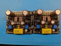
I take the opportunity to thank again Project16 for his contribution to the USSA5 PCB layout👍.
And glad you are back on this forum.
Fab
And glad you are back on this forum.
Fab
... I am at the point to install the power transistors. I will have to wait for the chassis to arrive in order to go for the next steps. Also, waiting for the PSU PCBs. I will update when I have something to show.
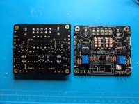
BEFORE soldering on the MOSFET's ,
The board should be mounted on the heat sink , with the MOSFET's in place , on the thermal pads .
Soldering on MOSFET's is the last step .
Mounting the board
For some reason 3 x 0.5 mm machine screws have become a standard - with 50.8 tpi - which I think is too fine .
Consider using 4-40 machine screws instead .
I used 6mm long stand offs
Harwin 4-40 UNC x 6mm R44 - 1000602
But with probably need to use longer stand offs ... depending on the thickness of the thermal pads .
Make sure the board is mounted , centered on the heat sink , with the disconnects at the bottom .
If you gently clamp the heat sink on a drill press , drill the holes , keep it in place , then put the tap in the drill chuck .
Automatically the tap is lined up with the hole . Twist the chuck by hand to tap .
For a cutting fluid , synthetic motor oil seems to work fine .
Bend the leads of the MOSFET's around a form ... such as a drill bit ... maybe a 1/4" drill bit or smaller .
Before Soldering - there should be good surface contact between the MOSFET's , thermal pads and heat sinks .
6-32 machine screws will work with with Exicon MOSFET's , but there is no tolerance for error .
.
Actually , I've shown how a machinist student would set up drilling the holes in Post #2026 .
A reference line is scribed at the bottom , and all the other lines are measured wrt to that line .
Or if this were to go to a machine shop , they would probably use a milling machine to drill .
Holes would be drilled following co ordinates on a digital read out .
But I've been Completely out voted here , and people prefer the tracing out the holes method .
Either way , make sure the board is centered on the heat sink , and the disconnects are at the bottom .
Last edited:
Eliad ,
Since you already have a dual bench supply , if you plan to build more preamps or amps in the future ,
consider buying a used scope . You can probably find a good deal on an older Techtronix Scope and probes .
But know that the chassis of these scopes in connected to hydro earth .
Which means if they are connected to an amp's analog ground , analog ground is now connected to hydro earth
Also be aware that the contacts on older scopes tend to develop intermittent faults .
Then you could build a simple test generator .
Try to build circuits one stage at a time . When I started building the USSA 3.2 Amp ,
I soldered in the driver MOSFET's only , and slowly brought up the bias current on these .
If you had a test generator and scope , you could see a waveform and know the circuit
is working fine . Then solder in the Exicon MOSFET's .
.
- Home
- Amplifiers
- Solid State
- USSA-5 Build with Review