
Built the best I could so far with the schematic. Waiting for laterals from profusion, ordered May 1st, still havent shipped. I have a matched pair of jfets at 9ma idss. I know the damping will suffer. Should I get a set of jfets matched at 4.5-6 instead off ebay? This is a 3.2 build with FQA drivers.
Attachments

Good progress gsrchrisu
For the higher jfet IDSS value the effect on lowering the damping factor is already reduced by using the FQA drivers so you might get still the same or even higher DF than the original version 3.0. You might try it anyway like that and see how it goes. EBay is quite risky anyway to get genuine parts like that…. You ate better off with sellers on this audio forum or you can get the LSK/LSJ series which have also low IDSS value.
Fab
What is the lowest IDSS that I should consider? I have seen some at 4, is that too low. The sellers on ebay that I would use are punkydawgs or Truna?(he is on these boards, from Japan) I am going to try my 9's and see how it sounds.
Built the best I could so far with the schematic. Waiting for laterals from profusion, ordered May 1st, still havent shipped. I have a matched pair of jfets at 9ma idss. I know the damping will suffer. Should I get a set of jfets matched at 4.5-6 instead off ebay? This is a 3.2 build with FQA drivers.
Is R13 is missing ?
When ever bending metal , a form should always be used . So rather bending the leads on the MOSFET's freehand ,
recommend bending them around a 1/4 " drill bit .
I used a 6-32 machine screw to fasten the FQP3 MOSFET's to the heat sink .
The hole in the Exicon MOSFET's is large enough to accommodate a 6-32 , but there is no margin for error .
So consider using a 4-40 machine screws for the Exicons .
If you are waiting for the Exicon MOSFET's to arrive , you can still test the USSA 3.2 without them , as shown on post #92 .
Highly recommend using a dual bench supply for this , and start off with a low voltage supply rails .
Maybe +/- 10 Vdc . Keep an eye on the current when you switch on the bench supply , and slowly bring the supply voltage up to +/- 24 Vdc .
This allows you to get familiar with how the trimmers work .
Actually , I taped up the jeweler's screw driver , so if it was dropped , it wouldn't short anything .
I measured the voltage drop across the source resistors to obtain the bias current of the FQP3 MOSFET's .
.
Yes in the schematics r13 is crossed out and just RV1 is listed, but I see I would then possibly need to jump r13 to complete the circuit. I am also missing r19/20 since the values are not clear in the schematic. I planned on asking once I get back to working on the Pcb. I may PM you to ask some of your values and I am still not totally clear on setting the current for the FQA mosfets. Will def be trying first with no laterals and just a power supply. Profusion actually finally shipped today so hurray.
" I am still not totally clear on setting the current for the FQA mosfets. "
Gsrchrisu , I am absolutely no expert on this . However , as FAB coached me , the key is to look at the Yfs ( transconductance ) curve
of a MOSFET , which is not linear .
recall Yfs = delta Id / delta Vgs
https://electronics.stackexchange.com/questions/316397/change-of-transconductance-for-mosfet
The key is to set Id ( bias current ) high enough so that the MOSFET is operating on a section of the transconductance curve that is approx linear .
Unfortunately , the datasheet for the FQP3n30 doesn't show this curve .
https://www.onsemi.com/pdf/datasheet/fqp3n30-d.pdf
Have a look at my post #88 and #89 . I tested the USSA 3.2 without the Exicon MOSFET's , and had a look at the output on a scope .
When the bias was too low , there was a compression effect .
Note my DIY generator creates a waveform rises and falls based on the number e , its not a triangle wave .
Probably absolute minimum bias for the FQP's is somewhere around 55 mA .
So recommend testing the USSA 3.2 without the Exicon's , play around with the bias current and have a look on the output using scope .
Increase the bias current to when the waveform is no longer compressed and that's the minimum bias current .
.
Gsrchrisu ,
Actually , a similar story with jFET's . In this 2 part series , Erno Borbley says in order to maximize the linearity of a jFET ,
set Id = 60% to 70% x Idss ( figure 2B ) .
Highly recommend getting a print out of this 2 part series - its absolutely top notch .
https://audioxpress.com/article/JFETs-The-New-Frontier-Part-1.html
So if you are using jFET's with an Idss = 4 mA , should be looking at a bias current somewhere around 2.8mA.
.
I will be using jfets for idss = 9mA. I need to read through the instruction manual a couple more times 🙂 Usually Zenmod just tells me to measure x volts between a resistor for bias and I am good to go. I get this is a little more advanced.
My 2 cents , if FAB thinks the jFET's with an Idss of 4mA will work fine , I would go with these
because they will increase the Dampening Factor .
For the FQP3 MOSFET's , Ciss (typ) = 175pF which is very low and are easy to drive .
I've looked for a cook book equation on how much bias current is required to drive the Rgate x Ciss time constant
of the MOSFET's of the next stage , but haven't been able to find one .
.
Look what showed up today,wahoo. I got pink and orange. For any Canadians thinking about this, just these 4 laterals ended up being 125cdn to get here. 100 dollars for the 4 mosfets and 25 dollars in taxes and brokerage fees, that was using the 9 dollar US royal mail option. But can I really put a price on my happiness? Gonna skip starbucks for the next month LOL.
Attachments
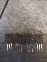
these 4 laterals ended up being 125cdn to get here. 100 dollars for the 4 mosfets and 25 dollars in taxes and brokerage fees,
that was using the 9 dollar US royal mail option.
Right now the British Pound has risen to $1.85 Cdn . That looks like the reason why the Exicon MOSFET's ended up costing a bit more .
First time I bought Exicon MOSFET's from Profusion , had them shipped by DHL and they dinged me with a brokerage fee .
Learned my lesson after this .
So the last time , I phoned Profusion and asked them to ship by Royal Mail .
Taxes were applied , but Canada Post did not charge a brokerage fee .
.
Gsrchrisu ,
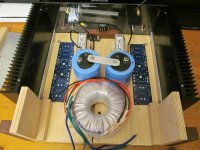
After building a number of tube preamps and the USSA 3.2 power amp
IMO the key to great piece of audio equipment is the power supply
For the USSA 3.2 , I used a DIY Audio Stores power supply board
However , after some listening tests , I'd say this is marginal .
Next improvement to a mono power supply would be to use
After building a number of tube preamps and the USSA 3.2 power amp
IMO the key to great piece of audio equipment is the power supply
For the USSA 3.2 , I used a DIY Audio Stores power supply board
- AnTek 600 VA transformer AN-6218
- VS-60APH03-n3 diodes
- 8 x 22,000uF caps
- Hammond 159ZL chokes and no dampening resistors .
However , after some listening tests , I'd say this is marginal .
Next improvement to a mono power supply would be to use
- LT4320 diode bridge controllers and MOSFET's
- 8 x 47,000uF caps .
- 2 x 300VA transformers
- 2 x power supply boards with 4 x 47,000 uF per board
- However , this means taking out the 2 chokes and replacing them with 0R1 resistors .
- AnTek 600 VA transformer AN-6218
- LT4320 diode bridge controllers and MOSFET's
- 2 x 100,000 uF caps with an ESR = 0.004 , these take the brunt of the ripple - but these are expensive
- 2 x Hammond 159ZL chokes and no damping resistor
- then each USSA board has its own cap board , 4 x 22,000uF per board
- use Belden 19364 for the internal AC connection because it has a shield
Attachments
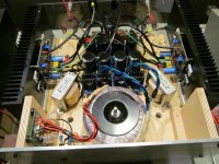
Note : If you look at the photo with the DIY Audio Stores board , you'll see the +Ve and -Ve power cables connected to the L Channel
are hung over the back of the case . These are connected to 3 Amp fast blow fuses .
Connecting fast blow fuses between the power supply , and the Amp being tested , has saved my back side on 3 occasions .
My strongest recommendation is to connect fuses when first testing the Amp .
A scope clearly shows the first bank of caps takes the brunt of the ripple .
Power is dissipated inside the cap because of this ripple , and this will affect the life expectancy of the cap .
So select caps that are designed for this application .
.
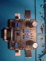
Very impressive, those are huge capacitors. I will be trying something completely different. My dual mono setup will have 160va transformers feeding 4 Tombo R25 power supply boards. Yes just 4 capacitors at 22000uf each. The power supply is the easy part for me, I am more concerned with getting the boards up and running. Hopefully I can mount the boards on the heatsinks and figure out how to test without the laterals. Will be using a VRDN board as my temp power supply to test the boards before hooking everything up.
Attachments

Hi gsrchrisu
160VA transformers rating is not that much… I suppose the Tombo R25 are voltage regulator boards?
To test without the output stage latéral is precisely the uniqueness of my build manual to test at different steps of building instead to wait at the end of assembly and not having a clue what mistakes have possibly been done…..
Refer to section 9 “Test front end without output transistors:”
However, since the manual does not cover for version 3.2 you should measure differently:
“9.2 Voltage/current measurements:
9.2.1 Adjust voltage in driver stage
• Connect V+ and V- and PGND and GND to power supply (from 15Vdc to 30Vdc).
• Adjust P2 for about 0,7 Vdc between TP6 and V-
• Adjust P1 for about 1,0 Vdc between TP5 and V+.”
But before testing these part of the build you should test first the input stage of section 8 “Test Input stage”…
Also installing the test point leads will help in the measurements…
Good luck
Fab
Last edited:
I have been using dual 160va for most of my first watt clone builds, I figured since most of the First watt 25w class a amps come with single 300va transformers. I may upgrade in the future. Thank you for those numbers, I will be mounting the board on the heatsink with just the drivers first. I will come back here with pictures and questions. With regards to setting final bias, I believe the value is 0.5 to 0.65mv. The version I am using has 0.01 resistors at r15 and r16, So does that mean 0.13mv to get 1.3a of bias? My math could be upside down here. No worries I know the final bias setting will be a ways off, I will try to make sure I have all the other values before.
Thank you for your help
Thank you for your help
Last edited:
- Home
- Amplifiers
- Solid State
- USSA-3B new Version based on USSA-3