Aha 0404, sorry my mistake.
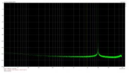
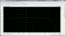
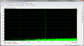
Here is my 2i2, signal from Viktor's 10kHz osc:

It's possible to reach -100dB 2nd by lowering input and increase gain (noise penalty). I bought the 2i2 mainly for acoustic measurements and for that it will suffice. Surface3 + 2i2 + MIC = light portable solution.
Now we are awaiting Lynx e22 results.
The 0404 is about 10 dB better than that, looped back, using its own DAC as the source.
Demian,
There is a potential problem with the left channel because a trace runs close to a buck converter iirc, but I didn't change that. It may show op as a series of spuriae at higher frequencies.
I did change the opamps in the output, and the left input channel because that was easier to access, eight in all. I used the 1652, but in hindsight it might have been better to go for the BJT input 1662. The 1652 has pretty bad 1/f noise, with a corner @ 1kHz, and I think it shows up in the measurements. I might try the 1662 on another 0404 I have.
To get the old chips off (JRC 5532 and 2068), I found it necessary to first cut the legs off and then desolder the feet. I tried to lift off the first chip in one piece and this pulled a trace off, which I could fortunately repair.
I have the equipment to modify the 0404. This is the best info on internals and modifying the 0404 I have found: http://www.diyaudio.com/forums/equi...tifacts-peaks-left-channel-7.html#post4175625
I currently have both 1212M and 1616M plus PCI and cardbus interfaces for them so I'll be putting my efforts there for now. The detailed scematic of the 0404 should help me figure out the input circuits of the 1616m.
What I've learnt so far from this thread.
The most suitable inerface for me (loudspeaker and noise measurement)
is Steinberg U12.
It wasn't mentioned here,
but featured on the linked Russian site that did various
RightMark Audio Analyzer tests.
Here are the features for 99$:
Testing device Steinberg UR12
Sampling mode 24-bit, 44 kHz
Interface MME
Testing chain Loopback
RMAA Version 6.4.2 PRO
20 Hz - 20 kHz filter ON
Normalize amplitude ON
Level change -3.0 dB / -3.0 dB
Mono mode OFF
Calibration singal, Hz 1000
Polarity correct/correct
Frequency response (from 40 Hz to 15 kHz), dB +0.00, -0.00
Noise level, dB (A) -97.2
Dynamic range, dB (A) 97.3
THD, % 0.0005
THD + Noise, dB (A) -91.1
IMD + Noise, % 0.0038
Stereo crosstalk, dB -97.6
IMD at 10 kHz, % 0.0041
No balanced outs. Rca only. One mic in and and One Hi-Z in (unbalanced)
Question: is one input and output enough for usual audio diy practice?
What I've learnt so far from this thread.
The most suitable inerface for me (loudspeaker and noise measurement)
is Steinberg U12.
It wasn't mentioned here,
but featured on the linked Russian site that did various
RightMark Audio Analyzer tests.
Here are the features for 99$:
Testing device Steinberg UR12
Sampling mode 24-bit, 44 kHz
Interface MME
Testing chain Loopback
RMAA Version 6.4.2 PRO
20 Hz - 20 kHz filter ON
Normalize amplitude ON
Level change -3.0 dB / -3.0 dB
Mono mode OFF
Calibration singal, Hz 1000
Polarity correct/correct
Frequency response (from 40 Hz to 15 kHz), dB +0.00, -0.00
Noise level, dB (A) -97.2
Dynamic range, dB (A) 97.3
THD, % 0.0005
THD + Noise, dB (A) -91.1
IMD + Noise, % 0.0038
Stereo crosstalk, dB -97.6
IMD at 10 kHz, % 0.0041
No balanced outs. Rca only. One mic in and and One Hi-Z in (unbalanced)
Question: is one input and output enough for usual audio diy practice?
IMO & IME, no.
Can someone help this lost boy. I remember having seen just the other day schematics of the EMU 0404 including the Bill Witlock style bootstrapping of common mode impedance, but I can´t find them again. Could somebody please provide me with a link? Thanks (multiplural) ahead.
Thank you very much Anders, just couldn't find it. And of course to Sidiy to sort this all out.
One of the reasons I wanted to have a look at it again is because I don't understand half of the connection of U15A, the Whitlock bootstrapping opamp. The output that goes to R44 makes sense to compensate for impedance mismatch at higher frequencies.
The connection that goes through R57 to earth doesn't in my mind. Firstly, the XLR input gets compensated twice. And it doesn't do anything for the TRS input. Any thoughts on that? I might try to lift c40 and c26 and see what happens.
Another thing I am considering is to get rid of the 48 V connection, so that c12 and c17 could be shorted, while still having the XLR inputs as an option.
One of the reasons I wanted to have a look at it again is because I don't understand half of the connection of U15A, the Whitlock bootstrapping opamp. The output that goes to R44 makes sense to compensate for impedance mismatch at higher frequencies.
The connection that goes through R57 to earth doesn't in my mind. Firstly, the XLR input gets compensated twice. And it doesn't do anything for the TRS input. Any thoughts on that?
TRS input has high input impedance so there should be less need to increase CM impedance (it is already fairly high). But I agree, why double bootstrap (XLR)? Why bootstrap between internal nodes (TRS)?
Correct schematic?
Strange

Thank you very much Anders, just couldn't find it. And of course to Sidiy to sort this all out.
One of the reasons I wanted to have a look at it again is because I don't understand half of the connection of U15A, the Whitlock bootstrapping opamp. The output that goes to R44 makes sense to compensate for impedance mismatch at higher frequencies.
The connection that goes through R57 to earth doesn't in my mind. Firstly, the XLR input gets compensated twice. And it doesn't do anything for the TRS input. Any thoughts on that? I might try to lift c40 and c26 and see what happens.
R44, but more relevant, R57 seems to be driven by unity gain op amp U15A through coupling capacitors C26 and C40.
The U15A op amp receives its input from the junction of R89 and R90 which are connected to the outputs of U9A and U9B which are supposed to have equal and opposite signal voltages that will cancel out if R89 and R90 are reasonably well matched.
Usually bootstrapping involves feeding back a significant signal voltage which under normal conditions should not happen here.
I am mystified.
Last edited:
Thanks. I'll look for other option
I just won a Mackie Black Jack USB on eBay - it should be here for testing early next week.
After a full mod this is my latest measurement:
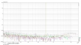
It seems to beat the Lynx. That card has more consistent readings overall, albeit at a slightly higher level of distortion.
The modifications consist of:
- changing the input and output opamps to OPA1652
- disconnecting the soft limiting circuit
- removing R89 and R90, removing C40 so that this mystifying part of the circuit is out of the loop.
I also tried moving input caps c12 and c17, which did not make any difference at all, so I put them back in. This also goes to show that AC coupling through a large electrolytic isn't something to worry about.
Edit: one thing I found which may be usefull to other EMU owners is that at full scale output -0dB Fs- the generator produces much more distortion than at -6dB. All measurements are therefore made with the latter output setting.
Last edited:
After a full mod this is my latest measurement:
View attachment 496579
It seems to beat the Lynx. That card has more consistent readings overall, albeit at a slightly higher level of distortion.
The modifications consist of:
- changing the input and output opamps to OPA1652
- disconnecting the soft limiting circuit
- removing R89 and R90, removing C40 so that this mystifying part of the circuit is out of the loop.
I also tried moving input caps c12 and c17, which did not make any difference at all, so I put them back in. This also goes to show that AC coupling through a large electrolytic isn't something to worry about.
Edit: one thing I found which may be usefull to other EMU owners is that at full scale output -0dB Fs- the generator produces much more distortion than at -6dB. All measurements are therefore made with the latter output setting.
Hi Vacuphile,
Great performance! Can you also show 10kHz FFT?
Ok, made some pics.
This one shows the output opamps replaced by OPA1652. Someone suggested OPA1612 might be better and I agree, but at 6 Euro's each they are about 3 times more expensive than the 1652.
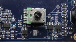
What this does is reduce the upward sloping distortion somewhat, but the effect on total distortion is limited.
The next pic shows how the soft clipper is cut of from the circuit.
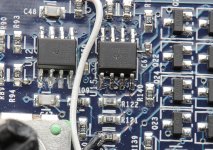
As this is basically a distortion engine for elevated input levels, as may be expected, taking it out of the circuit does lower distortion also at non-clipping levels. Also visible are the OPA1652's, replacing the JRC's. These have a form factor unique to JRC, but SOIC's align without problem.
Finally, capocide on numbers 26 and 40 eradicates the Whitlock style bootstrapping. For short measuring probes I see no advantage in this setup, but I can miss the positive feedback it gives for unbalances inputs like a sore tooth. It also eliminates the double bootstrapping to a node that is buffered from the input by U1 anyways.
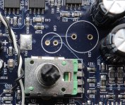
Since the loop back distortion of this setup is almost an order of magnitude larger than that of the OPA1652 opamps I used, I don't think much can be gained by replacing them by 1612's or LM4562's, but than again, you just might push distortion even lower by a teeny-weeny bit. The ADC is specced as THD+N=-103dB, but S/N is -114dB. The DAC is -100dB and -120 dB respectively. So, in all likelihood, -114 dB is the absolute minimum distortion that can be achieved. With all these mods, the EMU almost reaches that level at some points.
This one shows the output opamps replaced by OPA1652. Someone suggested OPA1612 might be better and I agree, but at 6 Euro's each they are about 3 times more expensive than the 1652.

What this does is reduce the upward sloping distortion somewhat, but the effect on total distortion is limited.
The next pic shows how the soft clipper is cut of from the circuit.

As this is basically a distortion engine for elevated input levels, as may be expected, taking it out of the circuit does lower distortion also at non-clipping levels. Also visible are the OPA1652's, replacing the JRC's. These have a form factor unique to JRC, but SOIC's align without problem.
Finally, capocide on numbers 26 and 40 eradicates the Whitlock style bootstrapping. For short measuring probes I see no advantage in this setup, but I can miss the positive feedback it gives for unbalances inputs like a sore tooth. It also eliminates the double bootstrapping to a node that is buffered from the input by U1 anyways.

Since the loop back distortion of this setup is almost an order of magnitude larger than that of the OPA1652 opamps I used, I don't think much can be gained by replacing them by 1612's or LM4562's, but than again, you just might push distortion even lower by a teeny-weeny bit. The ADC is specced as THD+N=-103dB, but S/N is -114dB. The DAC is -100dB and -120 dB respectively. So, in all likelihood, -114 dB is the absolute minimum distortion that can be achieved. With all these mods, the EMU almost reaches that level at some points.
Another thing to consider is when using an 0404, change the default sh*tty pot meters to some nice multiturn bourns pots. They are waaay to sensitive to calibrate your equipment to 0db levels.
- Status
- Not open for further replies.
- Home
- Design & Build
- Equipment & Tools
- USB vs PCIe Sound Card for audio analysis
