JLSounds I2SoverUSB V3Any pcb simliar to amanero with native dsd with better quality?
http://jlsounds.com/i2soverusb.html
I need native DSD. I don't have Thesycon drivers or I would have to buy them. DAC use DSC2 board
JL sounds crystals can be similar to amanero. I would like Crystek CCHD957 or AS338 or higher
JL sounds crystals can be similar to amanero. I would like Crystek CCHD957 or AS338 or higher
2adiaz What is your scope's bandwidth? How are you grounding the probe? What is the probe capacitance?
Reason I ask is that clock pulses are best measured with a low capacitance FET probe, using a spring ground probe as close as possible to the measurement point (don't use a wired ground clip), and using a high bandwidth scope (hopefully greater than 100Mhz bandwidth).
Regarding clocks, NDK SDA can be pretty good especially hand selected ones. That's what I2SoverUSB uses. Crystek works best if powered, bypassed, and loaded properly. IME most people are not getting the best possible from their CCHD-957 clocks.
Perhaps it would be a good idea to read the specs and check out the website - JLsounds does native DSD (upto DSD512), Thesycon driver is downloadable and there is an option to use Crystek oscillators via an add-on board.I need native DSD. I don't have Thesycon drivers or I would have to buy them. DAC use DSC2 board
JL sounds crystals can be similar to amanero. I would like Crystek CCHD957 or AS338 or higher
Hi
I have tested ndk SD and SDA oscillators instead of the original mounted osillators on the amanero board and yes the Sound improve with NDK SD but improves even further with NDK SDA. My current amanero serup is using the NDK SDA. For mounting you Will to remove the old osc by using hot air and Then make a small add on board with the NDK SDA.. it is not an easy opration but the improvement isreally to go for.
I have tested ndk SD and SDA oscillators instead of the original mounted osillators on the amanero board and yes the Sound improve with NDK SD but improves even further with NDK SDA. My current amanero serup is using the NDK SDA. For mounting you Will to remove the old osc by using hot air and Then make a small add on board with the NDK SDA.. it is not an easy opration but the improvement isreally to go for.
Thanks for answering me.
I use a Rigol DS1054. And the probes are the original ones from Rigol. Yes, I use the clip-on ground clamp connected to gnd near the crystal. I have measured 20mhz other times and I did not see such a bad signal.
I think CCHD957 and AS338 are better crystals, the problem is to remove the original ones from amanero. I can make a new small pcb with CCHD957 or AS338 with better power supply and connect wires to the pcb in a way. But I have neither the means nor the ability to do such small things...
Original Amanero works well and is very reliable, but they could leave four pads on the pcb (enable and out x2) for better external clock option.
IME it takes some R&D to get CCHD957 sounding their best. Diyiggy was right when suggesting 805 SMD acrylic bypass caps. I would add to that, avoid ferrites in series with the power rail. Also, don't rely on the clock enable pins to switch between clocks. They both need to be fully running all the time for phase noise to settle to minimum values. Switch clock outputs with a small relay. Iancanada's best clock switch using a small RF relay for that purpose. There are other things to know as well. IME the type of clock board shown in the youtube link above is a waste of time. May as well stick with I2SoverUSB and its stock NDS SDK clocks, it will sound better that way. IMHO I2SoverUSB is a better and slightly lower cost USB board than Amanero, anyway. Best low cost improvement for Amanero boards is to power them from clean 5v power instead of USB power. All the foregoing only my personal opinion. YMMV.
Yes my original amanero boards are running on clean low noise power supply. Cut a piece of pcb track to separate the 5v power from the usb.
But I would like to improve to Crystek or AS338 clocks, amanero is very reliable (several years without problems) and also it can be connected directly to my DSC2 dac, with different JL sounds pinout and I would have to wire it and some other small modification to be able to work with DAC dsc2.
Anyway I don't rule out the JLsounds option, I'll keep it in mind.
Thanks for explaining how the two clocks work better all the time and try to always leave both clocks working, I will look at the option of switching the two outputs with a special micro relay, thanks for such important information.
I thought it was better to use "enable" on each crystal
In amanero, the outputs of each clock have independent inputs on the XC2C64A-5VQ44C chip.
I thought it was better to use "enable" on each crystal
In amanero, the outputs of each clock have independent inputs on the XC2C64A-5VQ44C chip.
Last edited:
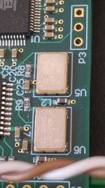
My use when I listen to music is always with HQplayer and dac dsc2. I think I am always using only the 22.579Mhz frequency. (the other one doesn't)
I could upgrade just that crystal and leave the other one unchanged (untouched), removing R9 if I could solder a wire there from another pcb made with cristek CCHD957 or AS338.
If maybe the other watch would also be used. Could you put both clocks running at the same time? It's possible? Maybe it can, I don't know.
Which do you think is better Crystek or Accusilicon?
Attachments
Last edited:
Regarding the common USB board practice of buffering clocks through a CPLD chip, that's always going to worsen phase noise from what good clocks are capable of. Best to move the clocks off the USB board, configure the USB board to accept an external master clock signal derived from your own master clocks. Then reclock the I2S signals through D-filp flops using your clean master clock signal as the last step just before running I2S signals into the dac chip. This kind of thing has been known in the forum for a long time.
I totally agree. but I don't know how to do that with the amanero. I know that the ideal is for the clock signal to go directly to the dac, but as you say it must be synchronized with the rest of the data.
If there is concrete information with what it says and in a amanero or another DDC, I would appreciate it if you could tell me.
Thanks.
If there is concrete information with what it says and in a amanero or another DDC, I would appreciate it if you could tell me.
Thanks.
I don't know how CPLD works in amanero.
Perhaps if the original clock inputs on the CPLD were used for reference only without modifying the post-out time, I could connect the clock outputs directly to the DAC and the CPLD at once?
Perhaps if the original clock inputs on the CPLD were used for reference only without modifying the post-out time, I could connect the clock outputs directly to the DAC and the CPLD at once?
Last edited:
Clock signals are RF and need transmission lines to transport them around to load devices. Often best to buffer clocks with ultra-low phase-noise buffers, then send one buffered clock signal to each destination device. The clocks will be more stable that way too, since there will not be too many reflections returning to their output pins. One good buffer chip is sometimes seen around the forum is NB3L553-D. https://www.onsemi.com/pdf/datasheet/nb3l553-d.pdf
Unfortunately, sound descriptions like the above don't provide any meanings to those who weren't there at that time. As the saying goes, one man's trash is another man's treasure. Unless there is something common to reference off of, it's useless.IME it takes some R&D to get CCHD957 sounding their best.
...
it will sound better that way.
In the dac dsc there are buffers on the clock line to greatly reduce the load on the output of the clock.
if you use Crystek 957 and Accusilicon AS318 at the same frequency than both has same phase noise specs so sound difference should be very little and it will be difficult to say witch one is best.My use when I listen to music is always with HQplayer and dac dsc2. I think I am always using only the 22.579Mhz frequency. (the other one doesn't)
I could upgrade just that crystal and leave the other one unchanged (untouched), removing R9 if I could solder a wire there from another pcb made with cristek CCHD957 or AS338.
If maybe the other watch would also be used. Could you put both clocks running at the same time? It's possible? Maybe it can, I don't know.
Which do you think is better Crystek or Accusilicon?
The AS338 has better phase noise compaired to both 957 and AS318. From my experience the AS338 will sound best. More analog sound, darker background and better seperation between instruments for just say a few improvements.
The Amanero has OE pins on the current OSC. I suggest to use these as then only one of the OSC will then have Output enabled. If you have both OSC enabled at the same time it will cause interference between the osc frequencies and intermodulations products will show up and this will result in higher Jitter level and this is not to be preferred.
Also please make sure to decouple between VCC and GND on the OSC and do the decoupling as close to the VCC ad GND pinds as possible. Using SMD caps for this propose is best as these have no leadouts.
One thing that concerns me is that the AS338 can't be found on Accusilicons web site. The AS318 can be found. so i would contact Accusilicon to confirm the As339, before buying some of the AS338's as they may be counterfeits or Custom parts that Accusilicon don't want to publish on the web site.
Also the phase noise spec of the 957 and the AS318 is very very good and showing the phase noise levels of the AS338 where the phase noise levels is around 10dB better.
Br
Caad
Phase noise measurements by Andrea Mori show that leaving both oscillators running and using dual layer relay switching is optimal. Listening tests confirm that relay switching works fine. Theories about interference between oscillators is speculation as to one effect might be worse than some other effect. Iancanada also designed with relay switching and found it to work fine according to his own jitter measurements. A lot depends on care in implementation, of course.
Regarding using Amanero with external clocks, firmware options and instructions at: https://amanero.com/combo384_firmware.htm Read the instructions in the firmware zip files for more info.
Regarding using Amanero with external clocks, firmware options and instructions at: https://amanero.com/combo384_firmware.htm Read the instructions in the firmware zip files for more info.
Hi MarkPhase noise measurements by Andrea Mori show that leaving both oscillators running and using dual layer relay switching is optimal. Listening tests confirm that relay switching works fine. Theories about interference between oscillators is speculation as to one effect might be worse than some other effect. Iancanada also designed with relay switching and found it to work fine according to his own jitter measurements. A lot depends on care in implementation, of course.
Regarding using Amanero with external clocks, firmware options and instructions at: https://amanero.com/combo384_firmware.htm Read the instructions in the firmware zip files for more info.
FYI. Ian Canadas Fifopi do not have rf switches. Ian used the OE pin to change OSC. also please for intermodulation products. it is correct you can include a RF-switch. please be aware that the pcb-layout must be optimized as high isolation between the osc frequency is required to not have any interrogation. So the easiest way to get the to OSC working optimal is using the OE pins on the OSC's. 🙂
Hi caad,
FIFO_Pi ver. 3 supports OE pin clock switching and or electronic switching (perhaps using the OE pin on NB3L553-D clock buffers, as Allo did with Katana dac). It was later when Ian designed the squarer that can plug into FIFO_Pi that he added pads for miniature relays, including G6K(U)-2F(P)-RF(-S, -T) https://docs.rs-online.com/6f42/0900766b80dbddbb.pdf ). Measurements of non-RF versions of similar miniature relays showed stray coupling between open contacts to be about 2pf. With clock outputs nominally operating into 50-ohm lines, 2pf of coupling clock coupling into the 50-ohm impedance showed no audible effects (relay switching was compared to OE pin switching and to pin-header jumper clock output switching, with no audible differences found between the methods). In addition, Andrea Mori designed relay clock switching using two miniature signal relays in series which brings relay-related coupling between clock outputs down to negligible levels. Of course, RF layout techniques were also used.
OTOH, listening tests with various clock modules, including Accusilicon and Crystek, showed that using clock OE pins for switching could require a few days of continuous operation after an output was enabled before stabilization of jitter and or close-in phase noise down to audible limits occurred.
Listening tests were performed using a custom AK4499 dac operating in DSD256 mode.
Completely agree that using OE pins is the easiest way to switch clocks.
Last edited:
- Home
- Vendor's Bazaar
- USB to I2S 384Khz - DSD Converter