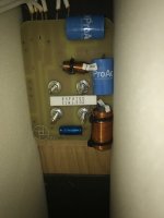
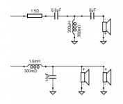
Sorry bout that !If you can post a photo taken from component side and indicate which wire go to which driver, it will be easier to draw a schematic.🙂
View attachment 1063946
the four wires to the right go to the woofers.
the two on the left is the tweeter.
does that help?
First put a jumper over 1R5 and listen if you like it that way. Then add 0.22uF over both blue capacitors. Then do what ever you want next. 
It would not be bad to do air core inductors if you make a new crossower, but to be approximately the same DCR as the existing ones or a little less.
For 1.63mH and 0.3ohm DCR a 1.8mm diameter wire is required. There is no chance that this new inductor will fit on that existing PCB.

It would not be bad to do air core inductors if you make a new crossower, but to be approximately the same DCR as the existing ones or a little less.
For 1.63mH and 0.3ohm DCR a 1.8mm diameter wire is required. There is no chance that this new inductor will fit on that existing PCB.
Last edited:
this good?Not completely. We want to draw a circuit diagram. We need to see where the components solder so we need a clean shot of the other side.
Or have you already drawn the schematic?
The tweeter looks like it is wired in opposite polarity
the lugs on the bottom pic on the left side are the red + side

First put a jumper over 1R5 and listen if you like it that way. Then add 0.22uF over both blue capacitors. Then do what ever you want next.
It would not be bad to do air core inductors if you make a new crossower, but to be approximately the same DCR as the existing ones or a little less.
For 1.63mH and 0.3ohm DCR a 1.8mm diameter wire is required.
i have the measurements of the inductors on the other thread.
dumb of me however that I didn’t measure both speaker inductors
wow. You rock man. Ha
You should have measured. However, they are wound automatically with the same number of threads so that they do not have large deviations, if they have the same ferrite core. When you wind a few air core inductors with the same dimensions and number of turns, they deviate very little, negligible.
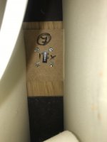
Yea through just plain contact with the boardDo the bolts connect electrically?
Do they go anywhere electrically? Look at the top left bolt hole on the track side where the resistor connects. How does that resistor connect beyond the board at that end (also the others)?
the tweeter is wired in reverse polarity
Last edited:
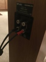
I'm going to assume they go to the amp as a "bi-wire with jumpers" set of terminal posts.
View attachment 1063963
yes that’s exactly what they do. By wire with jumpers

I'm going to assume they go to the amp as a "bi-wire with jumpers" set of terminal posts.
View attachment 1063963
is that with the tweeter in reverse polarity?
I'm still uncertain about polarity based on what I've read and seen. However it's often woofers normal and tweeter reversed.
I'm still uncertain about polarity based on what I've read and seen. However it's often woofers normal and tweeter reversed.
the tweeter is reversed. I just checked. Woofers normal
Funny I just measured the left speaker inductors.
tweeter is the same
bass. On the left is 1.50mH and DCR 0.3ohms
bass right is 1.63mH and DCR 0.3ohms
tweeter is the same
bass. On the left is 1.50mH and DCR 0.3ohms
bass right is 1.63mH and DCR 0.3ohms
Funny I just measured the left speaker inductors.You should have measured. However, they are wound automatically with the same number of threads so that they do not have large deviations, if they have the same ferrite core. When you wind a few air core inductors with the same dimensions and number of turns, they deviate very little, negligible.
tweeter is the same
bass. On the left is 1.50mH and DCR 0.3ohms
bass right is 1.63mH and DCR 0.3ohms
- Home
- Loudspeakers
- Multi-Way
- 'Upgrading’ my tweeters (can I do this?)

