at the summation point, the picture is not very good .
Protection will be more difficult to do
Protection will be more difficult to do
Attachments
Last edited:
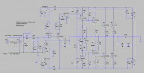
Can the collector of the 1st transistor (Q3 in my schematic, the one with Base at summation point) be connected to the ground, instead of +12V?
=============
Можно ли подключить к земле коллектор 1-го транзистора (Q3 на моей схеме, тот, у которого база в точке суммирования) вместо + 12В?
=============
Можно ли подключить к земле коллектор 1-го транзистора (Q3 на моей схеме, тот, у которого база в точке суммирования) вместо + 12В?
I thought you went to sleep 🙂
I know how this is going to end - you are going to add a coil to it...
Can the collector of the 1st transistor (Q3 in my schematic, the one with Base at summation point) be connected to the ground, instead of +12V?
=============
Можно ли подключить к земле коллектор 1-го транзистора (Q3 на моей схеме, тот, у которого база в точке суммирования) вместо + 12В?
option
Attachments

Exactly. I tried it, and it looks/works ok.
=====
Точно. Я попробовал, и он выглядит / работает нормально.
=====
Точно. Я попробовал, и он выглядит / работает нормально.
Now, that emitter follower you added (Q8 in my schematic) - it's currently operating at 100mW. Little bit too much for a small transistor, and not high enough for using bigger TO-126.
Perhaps it's power dissipation can be lowered somehow by 20%, so small transistor can be used?
=======================
Теперь этот эмиттерный повторитель, который вы добавили (Q8 на моей схеме), в настоящее время работает на 100 мВт. Немного многовато для маленького транзистора, и недостаточно высоко для использования большего ТО-126. Возможно, рассеиваемую мощность можно как-то снизить на 20%, чтобы можно было использовать небольшой транзистор?
That we have a composite transistor of the opposite conductivity turned out . The structure of the amplifier is equivalent to Sukhov
100mw normally.R47 change, increase to 510-750. Checking for the square wave and frequency analysis. A1145/C2705 A1208/2910
100mw normally.R47 change, increase to 510-750. Checking for the square wave and frequency analysis. A1145/C2705 A1208/2910
Last edited:
I don't see these transistors available in US, at least not from reputable sellers (E.g. Mouser, Digikey)..
============
Я не вижу этих транзисторов в продаже в США, по крайней мере, у уважаемых продавцов (например, Mouser, Digikey).
============
Я не вижу этих транзисторов в продаже в США, по крайней мере, у уважаемых продавцов (например, Mouser, Digikey).
>2N5401/2N5551 Excellent transistors
I have these.
Anything wrong with BC5xx ?
Or KSA992/KSC1845
Have plenty of them as well...
I have these.
Anything wrong with BC5xx ?
Or KSA992/KSC1845
Have plenty of them as well...
I only have 2n5401/5551 and BF420/421/422/423 a lot .Original ones. I won't say anything about the others.
2N3055 quasi version
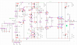
In a meantime, since I have some PCBs left, and a lot of 2N3055 transistors, I wanted to build Wiederhold77 quasi BJT version with 2N3055.
Rails at +/- 25V.
It was actually lot of trouble, because it seems that all 2N3055 models for LTSpice are old - I guess developed for original, epitaxial devices.
Modern devices are very different.
So while my spice model worked very well in theory, actual build was oscillating all over the screen, and I spent lots of time debugging it.
Finally, I found new models for 2N3055 (attached), and re-done the sim, and today the amp worked like a champ.
See screenshots.
Slew Rate is approx 13V/us. Slightly faster faster than first 3 amps.
Runs very stable, not hot, no heatsinks needed for drivers.
Idle current 25mA per device.
Music tests to follow.
So this is 4th amp built so far from this thread, I guess I have nothing better to do... 🙂
All tests done with 8 Ohm resistive load.
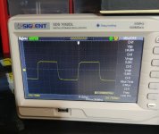
Sinus at 14kHz, 82kHz, 150kHz
Square at 14kHz
Output DC offset: -0.6mV
Op-amp was TL071.
In a meantime, since I have some PCBs left, and a lot of 2N3055 transistors, I wanted to build Wiederhold77 quasi BJT version with 2N3055.
Rails at +/- 25V.
It was actually lot of trouble, because it seems that all 2N3055 models for LTSpice are old - I guess developed for original, epitaxial devices.
Modern devices are very different.
So while my spice model worked very well in theory, actual build was oscillating all over the screen, and I spent lots of time debugging it.
Finally, I found new models for 2N3055 (attached), and re-done the sim, and today the amp worked like a champ.
See screenshots.
Slew Rate is approx 13V/us. Slightly faster faster than first 3 amps.
Runs very stable, not hot, no heatsinks needed for drivers.
Idle current 25mA per device.
Music tests to follow.
So this is 4th amp built so far from this thread, I guess I have nothing better to do... 🙂
All tests done with 8 Ohm resistive load.
Sinus at 14kHz, 82kHz, 150kHz
Square at 14kHz
Output DC offset: -0.6mV
Op-amp was TL071.
Attachments
-
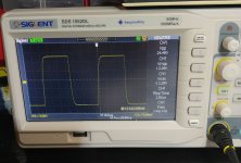 square_14kHz_24Vpp.jpg163.5 KB · Views: 324
 -
 square_14kHz.jpg151.3 KB · Views: 167
 -
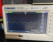 sinus_150kHz.jpg144.3 KB · Views: 164
 -
 sinus_82kHz.jpg153.3 KB · Views: 315
 -
 sinus_14kHz_34Vpp.jpg151.9 KB · Views: 346
 -
 whole_amp2.jpg354.1 KB · Views: 343
 -
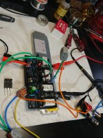 whole_amp1.jpg317.6 KB · Views: 485
 -
2n3055_spice_model.zip1.3 KB · Views: 128
-
wiederhold1977_quasi.asc10.7 KB · Views: 131
-
 wiederhold77_quasi_bjt.png44 KB · Views: 540
Last edited:

ONE REMARK. Diod8 remove or parallel to the emitter junction of the first transistor after opamp put the diode .otherwise, there may be problems. Well, put the diodes in the current sources. Posт № 943 diode
Last edited:
My previous builds also had this diode D8 at Q1 (E-B).
Should it be removed in all of them, or just this one is problematic?
It should be moved to Q10, anode to emitter, cathode to the base?
==========
В моих предыдущих сборках также был этот диод D8 на Q1 (E-B). Стоит ли его убирать во всех, или только с этим проблематично? Его нужно перенести на Q10, анод на эмиттер, катод на базу?

I don't have capacitors in parallel with LEDs...
Do you?
Attachments
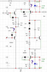
You'll understandWhat will happen if diode is left at Q1, as it is?
you'll understand. Diodes are not required in current sources in Sukhov without protection.In LMC and LP are mandatory
Attachments
Last edited:
- Home
- Amplifiers
- Solid State
- Unusual amp from 1987