In December, I will order. By the way IMD with 2 pairs
I would look at John Atkinson's face as he measures your amplifier. 😀
Last edited:
I'm slowly setting up my QuantAsylum 401 analyzer box, and learning how to measure...
Very soon I'm going to measure all my amps 🙂
The hour of truth is coming 🙂
Very soon I'm going to measure all my amps 🙂
The hour of truth is coming 🙂

You need a good notch filter and a generator with very low distortion. Or put spectraplus on your computer
No, not Igor. Akulinichev Ivan Timofeevich.Transistor VT4 germanium RF.
A similar displacement scheme was used in a number of designs by Dr. Igor Akulinichev. He called the current shunt circuit
Ivan or Igor - let them be; in the meantime I'm working on the aluminum chassis for Widerhold Quasi Hexfet 🙂
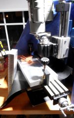
Machining the Alu plate (1 inch thick, 6 wide x 12 long).
Copper spreaders for fet pairs + heatsink..
Should be enough for honest 2 x 120W.
Machining the Alu plate (1 inch thick, 6 wide x 12 long).
Copper spreaders for fet pairs + heatsink..
Should be enough for honest 2 x 120W.
Attachments

Great work. Are vertically mounted transistors running without a heatsink?
All TO-126 transistors are lined up on the PCB on the purpose - there will be Alu heatsink going across both boards, and all these plastic transistors will be screwed to it - including temperature sensor BD139s.
MJEs and BDs will need mica isolators...
In reality only drivers need heatsinks (in the LatFet version no heatsinking was needed), but it won't hurt to have all of them cooled...
The introduction of the EP into the voltage amplifier gives a positive result. Even in the composite with Oramn.
Added a local OOS to the emitter of the second transistor.A completely different amplifier has become. Of distortion decreased
Tried to sim it in ltspice, so for no success..Heavy oscillations...
Скиньте файлик в лтс.Гляну,где причина
Give me the LTS spice file .I'll look at the error
I finished a purely discrete version .It is necessary to draw printed circuit boards
Give me the LTS spice file .I'll look at the error
I finished a purely discrete version .It is necessary to draw printed circuit boards
Last edited:
I'm basically fine with versions sim-ed and built so far.
Don't think there would be big difference in measurements/listening -
all these amps already have very impressive parameters.
If there is one thing I would like to improve - it's the slew rate.
So far - 15V/us measured - which matches the sim exactly.
But this I guess is limited by VAS configuration itself, not the input stage..
Just to compare I sim-ed square waves on discrete NMOS200 (blameless quasi hexfet that I built few years ago)
Power amp under development
which shows slew rate over 60V/us.....
15V/us is perfectly fine for an amp, but not impressive 🙂, perhaps more is possible?
Last edited:
I tried with these capacitors, they were making it even worse...
inductor in there? Not a resistor?
inductor in there? Not a resistor?

OK, it works fine with C10=330pF, C15=47pF, C16=68pF (referring to my asc file).
Not sure if this is optimal, will try to tune it up later on.
What kind of inductor it should be? Air coil? Or magnetic core?
Not sure if this is optimal, will try to tune it up later on.
What kind of inductor it should be? Air coil? Or magnetic core?
Total Harmonic Distortion: 0.000000%(0.000092%)
FFT also looks slightly better 🙂
>The gain is too high .We need to reduce it.
Now it works perfect even with my original gain (4k resistor in the input).
Wonder what slew rate will be. Will check later today..
FFT also looks slightly better 🙂
>The gain is too high .We need to reduce it.
Now it works perfect even with my original gain (4k resistor in the input).
Wonder what slew rate will be. Will check later today..
Last edited:
- Home
- Amplifiers
- Solid State
- Unusual amp from 1987