Maxim, how your Q3/Q5 are biased?
With 2 LEDs or regular diodes?
I think it makes a difference.
If I add R12/13 + R33 and change R10/R11 like in your last version, my thing doesn't work at all.
My Q3/Q5 are biased with 1 RED LED. Values of R10/R11 are sensitive to the voltage on emitters of Q3/Q5....
With 2 LEDs or regular diodes?
I think it makes a difference.
If I add R12/13 + R33 and change R10/R11 like in your last version, my thing doesn't work at all.
My Q3/Q5 are biased with 1 RED LED. Values of R10/R11 are sensitive to the voltage on emitters of Q3/Q5....
47 ohms in emitters. red led.Everything works. 47 is not enough ?In TO126 transistors are needed
offtop .I worked at night for more than 10 years.I'm used to not sleeping.
offtop .I worked at night for more than 10 years.I'm used to not sleeping.
Attachments
Last edited:
What is the current going though R14/R47?
What is D3/D4 ?
What's voltage on emitters Q1/Q2 ?
I can't switch to LF op-amp, it doesn't work with LT1056.
What is D3/D4 ?
What's voltage on emitters Q1/Q2 ?
I can't switch to LF op-amp, it doesn't work with LT1056.
Last edited:
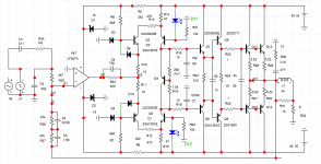
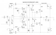
Evolution of Symmetrical LMK/Wiederhold77
While waiting for you to troubleshot previous schematic, here is modified one, with extra buffers added like in original Wiederhold.
Basically it looks like symmetrical Wiederhold, with slightly different biasing of the buffer.
Also fast, square waves very nice, and looks like it's more flexible.
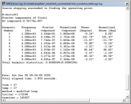
Distortions even lower than before.
Clip-protection diodes missing for now.
Previous version was simpler, perhaps it's still possible to make it work (it just doesn't work for me with LT1056).
While waiting for you to troubleshot previous schematic, here is modified one, with extra buffers added like in original Wiederhold.
Basically it looks like symmetrical Wiederhold, with slightly different biasing of the buffer.
Also fast, square waves very nice, and looks like it's more flexible.
Distortions even lower than before.
Clip-protection diodes missing for now.
Previous version was simpler, perhaps it's still possible to make it work (it just doesn't work for me with LT1056).
Attachments
Last edited:
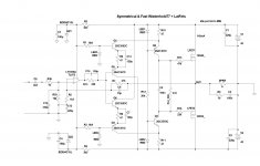
Yes, I have a version like this too. Check it out.
Same fast, square waves good.
Same fast, square waves good.
Attachments
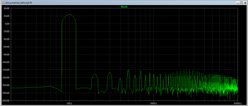
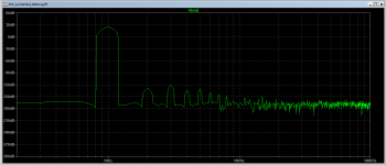
The spectrum is better then 'normal' Wiederhold, and it's 4 times faster.
So this is an improvement, at the cost of 2 transistors..
So this is an improvement, at the cost of 2 transistors..
I also run every LMK-like schematic you published here, especially the more recent ones through the sims, and I didn't see 60V/us anywhere...
But I was looking at Vpp 50V.
Schematic from which post?
You multiplied 15V in 250ns from your graph by 4, and you got 60V/us ?
You sure it works like this? 🙂
Maybe... I'm not sure.
But I was looking at Vpp 50V.
Schematic from which post?
You multiplied 15V in 250ns from your graph by 4, and you got 60V/us ?
You sure it works like this? 🙂
Maybe... I'm not sure.
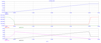
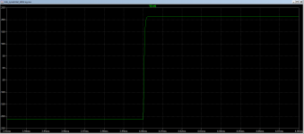
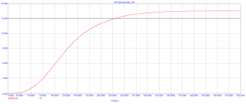
Maxim, I simmed again square waves of your LMK with inductive correction.
Square waves with amplitude of 15V show rise time slightly below 1us,
if I increase amplitude to 50V, rise time increases to 4us.
Also, with 50V amplitude some kinks are showing up on the square graph...
I guess you have to sim with higher voltage, not just 15V.
I don't know what are 'industry' standards, as far as testing with square waves goes... What amplitude is 'enough'?
Last edited:
The max slew rate is measured by high frequency and see at what frequency/amplitude the slope saturates. The input filter doesn't allow to measure by square wave.
A side question, what PCB software you use or advise me to use?
A side question, what PCB software you use or advise me to use?
A side question, what PCB software you use or advise me to use?
I recommend Sprint Layout 6.0 From Abacom
Sprint Layout 6.0, ELECTRONIC-SOFTWARE-SHOP
I think it's the easiest one, and offers all the features I ever needed.
It's not free though.
- Home
- Amplifiers
- Solid State
- Unusual amp from 1987