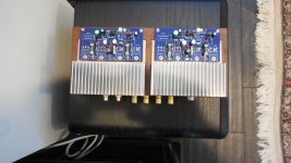
Working prototype
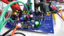
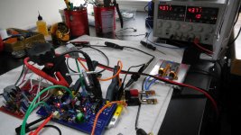
I tried 1st assembled board today.
Rails +/- 43V, idle current approx 35mA per 1 Latfet (100mA for whole amp).
All screenshots and measurements with 8 Ohm resistive load.
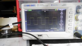
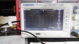
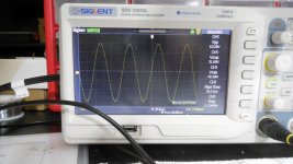
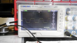
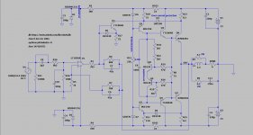
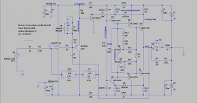
See attached waves. Everything worked without tweaking any values. Everything exactly as shown in the schematic/ltspice sim in post #172.
Output transistors are 2 pairs of original 2SK1058/2SJ162.
Clipping happens at approx 80Vpp.
All To-126 transistors running warm, but not hot. No heatsink needed.
Output voltage offset: 2mV
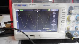
Slew rate > 10V/us - wouldn't mind higher value here..
I tried 1st assembled board today.
Rails +/- 43V, idle current approx 35mA per 1 Latfet (100mA for whole amp).
All screenshots and measurements with 8 Ohm resistive load.
See attached waves. Everything worked without tweaking any values. Everything exactly as shown in the schematic/ltspice sim in post #172.
Output transistors are 2 pairs of original 2SK1058/2SJ162.
Clipping happens at approx 80Vpp.
All To-126 transistors running warm, but not hot. No heatsink needed.
Output voltage offset: 2mV
Slew rate > 10V/us - wouldn't mind higher value here..
Attachments
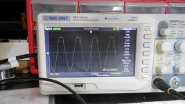
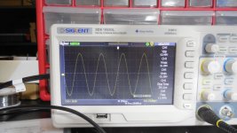
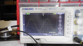
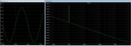
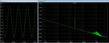
Few more waves added
Few more waves added.
Funny thing - I forgot to put opamp in the socket, and of course whole amp wasn't working.
Took me 10 minutes to realize my mistake 🙂
Few more waves added.
Funny thing - I forgot to put opamp in the socket, and of course whole amp wasn't working.
Took me 10 minutes to realize my mistake 🙂
Attachments

Last edited:
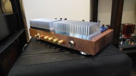
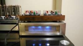
Completed chassis, playing music
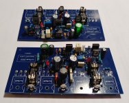
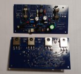
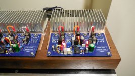
Finished Wiederhold77 LatFet amp (from post #172, but built with 2 pairs of LatFets).
This time - wooden (black walnut) chassis instead of metal,
but there is over 1 pound of thick copper plate under the PCBs connecting FETs to the heatsinks.
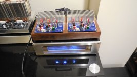
Plugged to the PSU, and playing music.
Excellent quality. Due to late hour can't test higher power levels; will
do tomorrow. Also will test sound of different op-amps, but with my tin ears it seems unlikely to detect any difference 🙂
Unfortunately this was my last batch of original Renesas LatFets...
Finished Wiederhold77 LatFet amp (from post #172, but built with 2 pairs of LatFets).
This time - wooden (black walnut) chassis instead of metal,
but there is over 1 pound of thick copper plate under the PCBs connecting FETs to the heatsinks.
Plugged to the PSU, and playing music.
Excellent quality. Due to late hour can't test higher power levels; will
do tomorrow. Also will test sound of different op-amps, but with my tin ears it seems unlikely to detect any difference 🙂
Unfortunately this was my last batch of original Renesas LatFets...
Attachments

these transistors are not available from Farnell, mouser or digikey. Is it possible to use IRFP(9)240?
Honestly, I don't want to use bipolar, less component count, I have plenty of IRFP(9)240.
Not really. For acceptable result you should use buffer for HEXFETs and VBE Multiplier as well. So you'll get same complexity.
I see, I did some simulation with HEXFETs, it becomes a completely different amplifier.. stanislav1957 was right.
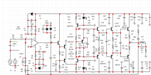
This is my version what I want to build. Nearly all of parts are in my stock. Toshiba's new TTC/TTA transistors with onsemi's NJWs are working good (I used them in my Blomley), so hopefully they will work in Wiederhold as well. Elvee's 2Si VBE multiplier is OK, however I can set Iq between 70 and 180 mA Only. The sweet spot is somewhere around 130mA according the simulation, so good enough. I'm going to design my PCB for this version.
Attachments
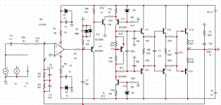
Familiar.Similar to my amp. It is desirable to have an emitter repeater after the output of the operational amplifier.better coordination between the op amp and the discrete amp
Very low level of distortion
Very low level of distortion
Attachments
Last edited:
This is my version what I want to build. Nearly all of parts are in my stock. Toshiba's new TTC/TTA transistors with onsemi's NJWs are working good (I used them in my Blomley), so hopefully they will work in Wiederhold as well. Elvee's 2Si VBE multiplier is OK, however I can set Iq between 70 and 180 mA Only. The sweet spot is somewhere around 130mA according the simulation, so good enough. I'm going to design my PCB for this version.
please share the asc file
Thank you Maxim. I tried to implement the emitter follower buffer to output of opamp, but something is wrong. Practically no distortion before clipping. This is nonsense. Would you share your final version?
Attachments
I don't understand you. Too little distortion?Thank you Maxim. I tried to implement the emitter follower buffer to output of opamp, but something is wrong. Practically no distortion before clipping. This is nonsense. Would you share your final version?
I don't understand you. Too little distortion?
Only a few in 20kHz, as you can see on attachment pix. At 1kHz is nothing.
- Home
- Amplifiers
- Solid State
- Unusual amp from 1987