The overcurrent on an output tube is possibly due to a shorted mosfet in its cathode. If the mosfet is good look for a wiring or component error in the parts feeding the gate of the fet. It is possible to troubleshoot the cathode mosfet circuit without an output tube, but a suitable path for current flow through the mosfet must be established by sticking a resistor into the tube socket from cathode to plate or possibly the screen grid pin. You only need a few mA so either should work, but I have only used the plate connection with a 6 inch long wirewound 50K resistor since I already had it. Make sure that you can adjust the cathode voltage from about 20 to 70 volts. These voltages are dependent on your actual B+ voltage.
Running a power pentode with screen voltage and no plate voltage is usually instant death for the tube since the screen grid gets to eat all the tube current and the 8068 has a rather tiny screen grid.
I have several used 8068's that I pulled from dead (left outside in Florida for a year) power supplies before scrapping them. They are on my list of tubes to try in the UNSET but I haven't got to them yet. There is much speculation on the internet as to what is actually inside the 8068. I have two distinctly different designs, and both are GE made. Some say its s 6L6GB with a big fat plate, and others say it's a 6CD6 with a 6L6GB cathode. I have some that could be described by either of these tubes. They both appear to have a 6L6 cathode though there are two distinctly different plates. If I find some bad ones in testing, they will meet the hammer for a look inside.
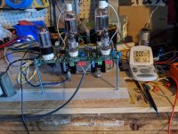
The UNSET on my workbench has been turned on several times for extended listening sessions. It is currently running a pair of 6LW6 tubes at around 42 watts of dissipation through Hammond 1628SEA OPT's wired for 2500 ohms. I like the way it sounds so I want to make a complete UNSET amp for daily use but am still somewhat undecided as to exactly what to build. Since 6LW6 tubes are getting scarce and expensive, I am hesitant to run them at 42 watts forever, so I may look at building an UNSET with two output tubes per channel. This all depends on what I can scrounge up for a chassis.
Running a power pentode with screen voltage and no plate voltage is usually instant death for the tube since the screen grid gets to eat all the tube current and the 8068 has a rather tiny screen grid.
I have several used 8068's that I pulled from dead (left outside in Florida for a year) power supplies before scrapping them. They are on my list of tubes to try in the UNSET but I haven't got to them yet. There is much speculation on the internet as to what is actually inside the 8068. I have two distinctly different designs, and both are GE made. Some say its s 6L6GB with a big fat plate, and others say it's a 6CD6 with a 6L6GB cathode. I have some that could be described by either of these tubes. They both appear to have a 6L6 cathode though there are two distinctly different plates. If I find some bad ones in testing, they will meet the hammer for a look inside.
The UNSET on my workbench has been turned on several times for extended listening sessions. It is currently running a pair of 6LW6 tubes at around 42 watts of dissipation through Hammond 1628SEA OPT's wired for 2500 ohms. I like the way it sounds so I want to make a complete UNSET amp for daily use but am still somewhat undecided as to exactly what to build. Since 6LW6 tubes are getting scarce and expensive, I am hesitant to run them at 42 watts forever, so I may look at building an UNSET with two output tubes per channel. This all depends on what I can scrounge up for a chassis.
Thanks George.
I got a few minutes this evening to poke at it .
Right FQPF9P25 tested short . Left tested fine (but maybe wasn't) . Replaced Right MOSFET.
Powered up with 6DQ5s. Started to raise bias current on Left and blew fuse.
Tried again. Another fuse. Pulled left FQPF9P25 and tested again, now tests short. Replaced.
Powered again, both channels fine , though bias in both channels is twitchy/hair trigger at desired 60mA.
Powered down to cycle it again to see where bias ends up. Pretty good. Just under 60mA after a few minutes.
Not exactly sure why the FETs went after running fine for these past few months but touching the heatsinks after powering down they were really hot. I plugged another heatsink (HS380) into the top of the existing one and tried again. Top heatsink started to get warm pretty quickly so this fix might work but i had to get on to other things and so will try it again as soon as I find a few minutes.
Good lessons learned here. Especially about Pentode G2s not being very good anodes. Got to remember that one : ) Thanks.
Last edited:
Has anyone a model for the FQPF9P25 ( https://www.mouser.it/datasheet/2/149/FQPF9P25-110839.pdf ), FQP4P40 ( https://www.mouser.it/datasheet/2/308/1/FQP4P40_D-2314130.pdf ) and FQP3P50 ( https://www.mouser.it/datasheet/2/308/1/FQP3P50_D-2314161.pdf )?
@Tubelab_com : could the IXTQ10P50P ( https://www.mouser.it/datasheet/2/240/ixys_s_a0001274014_1-2272713.pdf ) be used (if available) to test more local a-g1 feedback being able to dissipate more power and being able to swing more volts?
@Tubelab_com : could the IXTQ10P50P ( https://www.mouser.it/datasheet/2/240/ixys_s_a0001274014_1-2272713.pdf ) be used (if available) to test more local a-g1 feedback being able to dissipate more power and being able to swing more volts?
Powered up and sounding very good. It took a couple of hours to get there and I have two resulting questions.
1) Setting up the 6DQ5's bias was easy enough and put back into a system to play and getting no sound I checked driver voltages and found them at about 10VDC each. (They had originally been set to 125V)
Resetting them drove the output tube bias crazy and the see-saw interdependence made stable settings difficult until I went back to the initial setup guide of starting with the outputs pulled and biasing the input/drivers (6HB6 in this case).
Then putting in the outputs and setting seemed to work fine but in the end it doesn't convince me that nothing is going to start walking around at some point. Both 6HB6 bias voltage and 6DQ5 quiescent current are constantly changing enough to make me wonder if there's a problem waiting to happen again , or is that the way I should expect the board to run ?
Question 2) Even doubled , the heatsinks for the FQPF9P25's get stinging hot. The kind of heat that just remembering it makes the hair stand up. It's presently a 500VAC secondary into a choke input supply. I have to say I really like the sound the way it is. Maybe that heat is just the price that has to be paid, though I can't imagine the MOSFETs will take it forever.
After a couple hours of running I tested my heatsinks. I just used an electronic meat thermometer clipped to one, highest reading I saw was 42C. After turning off the amp and giving it a minute for the voltage to bleed down I could keep my hand on the heatsink for an easy 10 seconds so it's not getting extremely hot. This is running 6DQ5 and 6EJ7 with a B+ of 318VDC. Driver plates are set at 180VDC, current through the output tubes 104mA.
I have seen stability problems like you mention when R7 or R8 is too high a value or when R108/208 was too low. Usually the screen voltage collapses as well. Right now with 318VDC B+ and a 100V zener in D4 I have R7 at 1.6K and R8 at 24K ohm.
I have seen stability problems like you mention when R7 or R8 is too high a value or when R108/208 was too low. Usually the screen voltage collapses as well. Right now with 318VDC B+ and a 100V zener in D4 I have R7 at 1.6K and R8 at 24K ohm.
Thanks for that. I'm using B.O.M. values with a B+ a hundred volts higher than yours so it will take a little thought and experimenting to see how exactly how your figures translate .
The image of kitchen thermometer strapped to heatsink got a smile and also reminded me that a meter I got years ago came with a thermocouple probe that I haven't used (or seen) since then. Time to do some digging.
Your D4 voltage change is interesting. What plate current are you getting with that?
Right now I can't give more than a few minutes at a time with this project but will do my best to get at it whenever possible and report back.
Thanks
I have 2 UNSET boards setup. One using 6DQ5/6EJ7 and 320V B+ and the other using 26HU5/12GN7A using 430V B+. The board with 430V B+ has R7 3.3K and R8 42K also with a 100V zener in D4. I have tried the 56V zener in the BOM, 100V, and 150V. With either input tube I get slightly better performance with the 100V in place.
Currently using a CCS set at 5.8 mA for the 6EJ7 where it likes 180V on the plate.
Currently using a CCS set at 5.8 mA for the 6EJ7 where it likes 180V on the plate.
🙂...The image of kitchen thermometer strapped to heatsink got a smile and also reminded me that a meter I got years ago came with a thermocouple probe that I haven't used (or seen) since then. Time to do some digging...
Attachments

(Jeeps! I thought I'd posted this but nup. Wring agon.)
No time to put the amp on the bench but found the thermocouple and measured what I could in situ. Power FET mounting screws are just under 70ºC and heatsink half-way up the body is just under 60ºC. Certainly hot but by the data sheet well within temp limits. B+ is 460 so probably unnecessarily high but I was playing music while measuring and it does sound good.
While here might as well add:
Nice pic. and putting the heatsink on the under side, I originally didn't like the idea of heat flowing up into the board so kept them topside , but it wouldn't surprise me if at least a degree or two is from facing the tubes.
Starting to use my coffee breaks to search out this thread I got the impression from Tubelab's posts that the BOM values were based on running the circuit in the range I'm in so was confident they're a good place to start. With so many different tube possibilities though it's not surprising there'd be combis where different values would work better. I'm torn between satisfied listening and exploration. Perhaps best to wait until there's time to do a second build.
Thanks Spiggs. Good to read your posts.
I had a pair of fat bottle 36LW6 tubes in my board several months ago. They were powered by a separate SMPS, so it's easy to turn on only the output tube heaters. I saw a rise of over 5C on the heat sinks with all air movement in the room shut off. Minimal movement reduces that rise. I now have everything running on a single Hammond transformer which is a bit overloaded and generates plenty of heat by itself, so isolated temp measurements are not easy any more.Nice pic. and putting the heatsink on the under side, I originally didn't like the idea of heat flowing up into the board so kept them topside , but it wouldn't surprise me if at least a degree or two is from facing the tubes.
Unfortunately, most mosfets made today are optimized for switching use since that's where the market is. They have no specs at all for SOA, incorrect specs (ONsemi / Fairchild parts), no "DC" data on the graph, or the ratings are too low for continuous operation in the linear region for our use. Running a switchmode fet in the linear region is risky and some may fail. So far, I have had good luck (only blown one part so far) with the FQPF9P25's, but every batch, and every part in that batch is different, and heat is definitely a major factor in SOA failures. P channel parts rated for LINEAR audio amps or "current regulators" are rare and hard to get today. I got some Exicon FETS designed for audio amp use nearly a year ago but have not tested them since they are TO-247 parts which will not fit in the board.
That's where I'm at. I have one working UNSET amp built on the PCB house board, and one of the two DIY proto boards that still works sometimes, but is in bad shape. Every time I think about experimenting on my working board, I wind up listening to it and deciding to leave it alone. I do have two more production boards about halfway stuffed. IF I find a chassis in my "stuff" collection that will hold one or two boards and three large transformers, then at least one of the three boards gets turned into an amp.I'm torn between satisfied listening and exploration. Perhaps best to wait until there's time to do a second build.
I have one of those cheap IR thermometers from Amazon. I have tried both the isolated epoxy coated TO220 fets and an identical TO220 part with the exposed tab mounted with a thermal pad and "Artic Silver" thermal compound. In both cases the case of the part was 5 to 10 degrees C hotter than the sink itself. Oddly the isolated part was a bit cooler.
I feel that way with my 26HU5/12GN7A UNSET. It sounds good and measures well. Should probably just build a case for it although that will take some effort since there is a lot to pack in with the big choke, big cap, and smps along with the usual transformers....That's where I'm at. I have one working UNSET amp built on the PCB house board, and one of the two DIY proto boards that still works sometimes, but is in bad shape. Every time I think about experimenting on my working board, I wind up listening to it and deciding to leave it alone...
With the 6DQ5/6EJ7 UNSET I want to see if I can get the harmonic profile 2H dominant all the way to clipping like with the 26HU5/12GN7A setup. Right now it becomes 3H dominant around 3 watts of output. I have been playing with the driver tube plate voltage and current but have not found that to change the overall harmonic profile much if any.
Almost all my testing has been using a 3K loading on the OPT since every test using 1.5K resulted in very high THD and with 6K the output is low. One thing I did notice in the few tests using 1.5K with the 6EJ7/6DQ5 tubes was that the distortion profile remained 2H dominant so I decided to revisited that tonight. As before THD was much higher. Playing with the driver tube parameters did not yield any improvement so I turned to the feedback circuit and after playing with a number of values ended up at 680K ohm down from the 1M ohm resistor I was using before. Driver tubes are set at 200VDC on the plate with the CCS delivering 5.8mA of current. Output tubes set at 104mA for 28 watts total dissipation at idle. Like this THD at 1W is 0.5% so still more than double the current 12GN7A/26HU5 setup but nicely 2H dominant and within the range of good sounding setups I have tested before. The distortion profile remains 2H dominant all the way up to 16.5 watts output and clipping starts at around 17 watts driven from a DAC with a max output of 1.5V. A short listening session tells me it's worth giving this setup a longer listen.
I ended up trying a number of different feedback resistor values with the 6EJ7/6DQ5 tubes. My favorite combination is with a 500K feedback resistor and the 1.5K OPT load. THD at 1W is 0.44% and it will just touch 17W before clipping, always 2H dominant. The gain like this is too low to hit clipping with a 1.5V source so I am feeding it with a preamp that has a little gain.
One issue left to figure out with my 12GN7A/26HU5 UNSET. The current through the output tubes does not remain stable. If I let the amp run for an hour then adjust both tubes to 104mA it sometimes remains stable sometimes one tube will drift up to 108mA. I readjust and it remains stable for the listening session. Next time I start up the amp it will drift again. Same behavior using different tubes. I can't remember if the amp did this before integrating the CCS or not. The 6EJ7/6DQ5 UNSET does not do this.
Hooked a couple meters to the output tube bias points to monitor the amp more closely. I then let it warm up for an hour and checked it. I believe the amp is now gaslighting me.

Haha! Gaslighting tubes! I’m back from vacation in the boondocks without internet, so I’m reading your experiments with interest. I’m in George’s situation regarding a non-functional working area, but I hope to do the last few things needed to turn on the juice to my UNSET soon.
I noticed you have a heatsink bar across your CCS’s. Did you find it necessary to provide additional heatsinking, or is is just a remnant of your attempts to get a stable operating point?
I noticed you have a heatsink bar across your CCS’s. Did you find it necessary to provide additional heatsinking, or is is just a remnant of your attempts to get a stable operating point?
Ever look at stuff you built years ago and realize that just maybe the amp or whatever may be correct? It is said that there is a fine line between genius and insanity and I'm not sure which side I'm on sometimes.I believe the amp is now gaslighting me.
Pulling hundreds of chips out of scrap circuit boards, soldering about 400 of them onto some perf boards and then interconnecting them with tiny bits of wire over a nearly year long period to build a digital music synthesizer back in 1971 qualifies as insanity. The synthesizer was destroyed by my father in a drunken rage in a matter of minutes, but I salvaged some of the boards because they represented almost a year of my life. I still have them, but little else from the early years of my life.
My workbench is currently occupied with a large Roland JV-1000 music keyboard, which has a possibly terminal case of "Roland red glue disease." It was my daughter's in the late 90's before she abandoned it and all of her other music stuff. She used it to play and teach music to kids. The idea is that she can use it to teach her own kids how to play the keys.
Attachments
I did it to add some additional heat sinking but also to provide a place to mount a brace to the pcb. It makes me a bit nervous to have the legs of the CCS chip as the only thing supporting the heat sinks over the long term....I noticed you have a heatsink bar across your CCS’s. Did you find it necessary to provide additional heatsinking, or is is just a remnant of your attempts to get a stable operating point?
In my case I know the amp is correct.Ever look at stuff you built years ago and realize that just maybe the amp or whatever may be correct? It is said that there is a fine line between genius and insanity and I'm not sure which side I'm on sometimes.
...
The output tube bias on the 12GN7A/26HU5 UNSET amp has been nice and stable over the last 4 days. What seems to have worked was to adjust R110 last and use it as a balance adjust between the 2 tubes. So adjust left tube using R110, adjust right tube using R210 and let everything settle for awhile, I checked in after an hour. Then with meters on both R117 and R217 use R110 to set both tubes to the same current. More current for the left tube means less for the right tube and vice versa, not equally but one does impact the other on my amp.
George‘s byline used to say “I blow up things so that you don’t have to”. I’m waiting for that in regard to UNSET. (And yes, I know about Tubelab not making enough profit etc. I wish you did, but most of us are doing this for a hobby).
I’m in a holding pattern now with my UNSET build. Waiting for George to clear “My workbench is currently occupied with a large Roland JV-1000 music keyboard” and to get more involved in this thread “UNSET Beta Board Build”. When I signed up for this project I expected more involvement from George and more guidance on tube operating conditions, measurements, etc., and other UNSET prototype building tips.
I’m in a holding pattern now with my UNSET build. Waiting for George to clear “My workbench is currently occupied with a large Roland JV-1000 music keyboard” and to get more involved in this thread “UNSET Beta Board Build”. When I signed up for this project I expected more involvement from George and more guidance on tube operating conditions, measurements, etc., and other UNSET prototype building tips.
- Home
- More Vendors...
- Tubelab
- UNSET Beta Board Build