Yes, it tamed the voltage spike nicely. A little disappointed though that the soft start board I installed didn't do the job by itself. It has a 2 second delay from turn on switching between a current limiter for the soft start to direct pass through. Doesn't seem enough in this case. I put the CL-60 before the soft start board but now am thinking perhaps it would be better after so it only limits the voltage going into the transformer and not the smps that I am using for the heaters.
I realized I made an error here. I was using 75K ohm for R8 with the 56V zener in place and 42K ohm with the 100V zener. Remembered this as I was updating the UNSET board I have configured for 6EJ7/6DQ5 tubes. With the 6EJ7 I am going to try a CCS setup for 5.7mA in combination with the feedback mod and other changes. I am going to try for a more compact build with this one using a 290uF electrolytic for C2, a smaller Hammond 159T choke, and the heaters running off the 6V windings on the toroidal. If it's quiet enough for headphone and near field speaker use I could set it up as my office amp. If not I'll probably use it as my garage amp.
If you could make the delay longer the soft start board should do it. The 26HU5 has a 11 second warmup time before it will conduct normally, so the 2 seconds delay is likely not enough. You are right not to include the smps in the CL-60 .
Thanks for clarifying the value of R8 as 42k with the D4 100V zener (what zener did you use, 1w?). I am still trying to understand how that driver tube is working, and wanted to check the zener current with the values you used. With 244V across R8, Iz=5.8 ma. I couldn’t find the Iz min for a 100V zener, and assume it be at least 2 ma. That means we have <2 ma for each 12GN7a. Is that enough? I tried to check but haven’t found a datasheet that I could figure out.
I was wondering, why not take the voltage for the 12GN7 screen from Q1 output (and reduce as needed) that is already regulated at 180 v, rather than from C7 (which is much higher)?
I am using a 1.3W 100V zener.If you could make the delay longer the soft start board should do it. The 26HU5 has a 11 second warmup time before it will conduct normally, so the 2 seconds delay is likely not enough. You are right not to include the smps in the CL-60 .
Thanks for clarifying the value of R8 as 42k with the D4 100V zener (what zener did you use, 1w?). I am still trying to understand how that driver tube is working, and wanted to check the zener current with the values you used. With 244V across R8, Iz=5.8 ma. I couldn’t find the Iz min for a 100V zener, and assume it be at least 2 ma. That means we have <2 ma for each 12GN7a. Is that enough? I tried to check but haven’t found a datasheet that I could figure out.
I was wondering, why not take the voltage for the 12GN7 screen from Q1 output (and reduce as needed) that is already regulated at 180 v, rather than from C7 (which is much higher)?
Thanks for the suggestion regarding the soft start. I'll take a look and see if I can increase the warmup time and see if that does it.
Well managed to blow it up again doing something stupid. I knocked my source off the bench while the amp was on and the rca jacks pulled out sending a large buzz through the OPT at which point I switched it off. Plugged everything back together and it was not working with the same signs as a bad Q201 I have had before. Replaced that and I get current to the output tube now but driver tube screen voltage is ~50V instead of 100V and plate voltage is around ~120V on the right channel instead of 250V. I'll be poking around as best I can but what next would be the likely culprit?
OK never mind. It was Q201. Strange I have had this happen before. I replace it and it does not fix the issue, I replace it again and problem solved. I bought 10 of these from Digikey and it seems that every other one goes bad right after install. Am I putting too much heat on these? I should test all the ones I have let and see if they measure the same on my cheap Ebay tester. Also these seem to be the weakest link in the Amp as far as failures for me. Is there a more robust part I could use instead?
I was able to do some testing with various start up times for the soft start circuit. I tried 12, 20, and 30 second delay times. In each case when the soft start timed out and bypassed the inrush current limiter the voltage would spike to just over 500V then drop down to normal B+ levels. So it seems the soft start alone will not do it.

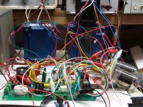
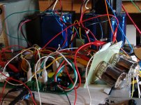
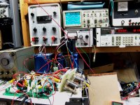
Slowly making some progress.
Just some details left, like winding the choke and OPT's 🤔

Just some details left, like winding the choke and OPT's 🤔
Thought about this and didn’t come up with much. However, I looked it up and VP0106 has a Gate-to-Source Voltage Max of +/- 20V! The voltage-divider bias pot probably prevents it but I wonder if the max could be exceeded at startup, even with the standard zener D4 (=56V). @spiggs, have you checked the voltages around the VP0106s? It would be good to know what the actual Gate-to-Source voltage behavior is. As you suggested, a more robust part might be good.OK never mind. It was Q201. Strange I have had this happen before. I replace it and it does not fix the issue, I replace it again and problem solved. I bought 10 of these from Digikey and it seems that every other one goes bad right after install. Am I putting too much heat on these? I should test all the ones I have let and see if they measure the same on my cheap Ebay tester. Also these seem to be the weakest link in the Amp as far as failures for me. Is there a more robust part I could use instead?
Regarding the behavior of your soft start circuit; it is puzzling indeed. Are you charging your main capacitors slowly via a resistor, that is bypassed by a relay after x seconds? What value? And the heaters on the 26HU5s are running full tilt during the “x seconds”?
Poking around the VP0106 the max I see at the gate is 8.5VDC, at the source 11.5VDC on startup.
The soft start I am using puts a current limiter in series that is bypassed after startup. There is something about how I had it wired in combination with a CL-60 only on the HV supply that still allowed for a startup voltage spike. I undid all that and am back to just using the soft start board with a inrush limiter rated at 20 ohm and 7A to feed both the HV and smps heater supplies for simplicity. The heaters are getting hot enough during the startup cycle that the 26HU5s are conducting and with a 25 second delay it now seems to have tamed the startup spike. With this the highest B+ I see during the startup cycle is 460VDC, this is just after the current limiter is bypassed.
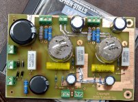
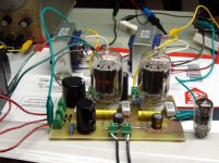
I bought a surplus Unlytic film cap rated at 290uF and 750VDC and now have that wired in for C2. Makes those motor run caps look puny but it does take up less space than 3 of them and has a stud mount on the bottom which I think will be handy. Don't notice any sound difference between the motor run caps and the Unlytic which is to say the amp sounds good with either in place.
The soft start I am using puts a current limiter in series that is bypassed after startup. There is something about how I had it wired in combination with a CL-60 only on the HV supply that still allowed for a startup voltage spike. I undid all that and am back to just using the soft start board with a inrush limiter rated at 20 ohm and 7A to feed both the HV and smps heater supplies for simplicity. The heaters are getting hot enough during the startup cycle that the 26HU5s are conducting and with a 25 second delay it now seems to have tamed the startup spike. With this the highest B+ I see during the startup cycle is 460VDC, this is just after the current limiter is bypassed.
I bought a surplus Unlytic film cap rated at 290uF and 750VDC and now have that wired in for C2. Makes those motor run caps look puny but it does take up less space than 3 of them and has a stud mount on the bottom which I think will be handy. Don't notice any sound difference between the motor run caps and the Unlytic which is to say the amp sounds good with either in place.
Despite blowing nearly every active part in my UNSET boards multiple times in 3 years, I have only blown one Q201. It was done however by plugging and unplugging the RCA cables (changing sources) with amp turned on and operating. In my case I just heard a pop and one channel went quiet.OK never mind. It was Q201. Strange I have had this happen before. I replace it and it does not fix the issue, I replace it again and problem solved. I bought 10 of these from Digikey and it seems that every other one goes bad right after install. Am I putting too much heat on these? I should test all the ones I have let and see if they measure the same on my cheap Ebay tester. Also these seem to be the weakest link in the Amp as far as failures for me. Is there a more robust part I could use instead?
The driver section of the UNSET board started out as an LTspice simulation. I used some random SMD p-fet in that simulation because it was a menu pick in the standard library. When it was time to make the first prototype I ordered 10 each of several similar mosfets in TO-92 from Digikey, intending to try them all and pick the best. The VP0106 was the first part to hit the test board. It worked, so I never looked back.
+/- 20 volts for max gate to source voltage is pretty typical for a small mosfet. +/- 30 volts is about the limit for large fets. Unfortunately all of my choices for mosfets including the VP0106 lack internal gate protection zeners. I believe that the charge build up on C101 / C201 is getting dumped into the gate of the fet when the input cables are messed with. It may be possible to reduce the value of R103 / R203 to provide a path for this current, but there is a trade-off with the size of C101 / C201 for LF response.
Regarding the behavior of your soft start circuit; it is puzzling indeed. Are you charging your main capacitors slowly via a resistor, that is bypassed by a relay after x seconds? What value? And the heaters on the 26HU5s are running full tilt during the “x seconds”?
The startup sequence in the UNSET board is complicated, and there are three distinct scenarios that all behave differently.I was wondering, why not take the voltage for the 12GN7 screen from Q1 output (and reduce as needed) that is already regulated at 180 v, rather than from C7 (which is much higher)?
In a typical amplifier the rectifier usually comes up first causing the power supply to be lightly loaded or unloaded. This lets the voltage rise to a high value that comes down when the tubes warm up. Each stage rarely has much effect on the others during warm-up. Most typical tube amps have subsequent stages operating out of phase with other since the typical gain stage inverts the signal. This is not the case with UNSET.
The plate of the output tube is connected to raw B+ through the OPT. It can draw unlimited current which is restricted only by the DCR of the opt and the power supply's ability to source current. The bias voltage for the output tube must be stable before the heater gets to operating temperature.
The driver stage operates in a similar manner except that its plate voltage is derived from B+ through a resistor or CCS chip. The plate voltage of the driver tube will be at B+ when the tube is cold, and drops at a fairly slow rate during warm-up to its eventual steady state value. This dropping plate voltage will ripple through the coupling cap pushing the output tube further into conduction if it is at operating temp before the driver tube. Oversize coupling caps are not your friend here. This can, and does cause a current surge in the output tube as the driver warms up, so ideally we want the driver circuit awake first.
Scenario #1 - Everything on a single power transformer, solid state rectifier, no start up circuit. This is what's on my bench now, a pair of 6LW6's into some Hammond 1628SEA's wired for 2500 ohms, fed by some 6HB6 drivers, all powered by a rather hot Hammond 272JX. Upon start up the current in the output tubes will rise to about 300 - 400 mA each. It then drops to 140 mA each (my chosen bias current). This gets me 20 WPC. The 6LW6's do see a rather rude surprise on start up, but this is similar to the treatment that a 26 or 36LW6 would get in a series string TV set where they were intended to live. The cathode is rated for 1.4 Amps peak and 400 mA continuous. A tube rectifier would likely not live through this start-up scenario.
Scenario #2 - Everything but the output tube heaters on a common supply with the output tube heaters on their own SMPS or transformer. This is probably the most common setup, and what I spent the most time with. Firing everything up simultaneously is similar to Scenario #1. I usually brought the board up first, then plugged in the SMPS for the output tubes to reduce the output tube current surge. Yes this will allow the B+ to rise momentarily, so the choice is a voltage surge or a current surge. I would choose to delay the output tube heaters a bit.
Scenario #3 Three separate power supplies, B+, driver tube heater, output tube heater. Fire the heaters up first, then the B+ and mess with the time constants to minimize the surges. R5 / C4 can be used to delay the screen voltage to the output tubes. This can be used to mitigate the start-up current surge.
The original test board had several extra resistors and capacitors that were removed to make a viable layout:
The current board had the output tube bias voltage derived from the regulated screen voltage. The original board had an additional resistor to main (before Q1) B+. A regulated voltage source for the screen and bias supply (the current design) keeps the output tube CURRENT nearly constant as the line voltage wanders. The tube dissipation will increase as the line voltage rises. Using two resistors to feed the bias pot can result in a constant DISSIPATION mode with changing line voltage. The optimum resistor values were individual tube dependent, so I abandoned this effort. At this time the R5 / C4 time constant affects both the screen voltage and the bias voltage. Separating the bias circuit to allow a longer time constant for the screen voltage may be beneficial and may be investigated as time permits.
I originally chose an electrolytic cap for C9. This was a mistake since the value must be small to avoid delaying the bias voltage creating a huge current spike at start-up.
I had a similar multi resistor setup for the driver screen, but eventually settled on a zener and resistor from raw B+ to minimize the driver start-up time.
That is how I blew Q201 up this last time. Every other time I was poking around that area with a probe so I chalked it up to a slip of the probe shorting something that caused it to fail. It does concern me a little since accidentally unplugging an amp is not out of the realm of possibility when it's in normal use.Despite blowing nearly every active part in my UNSET boards multiple times in 3 years, I have only blown one Q201. It was done however by plugging and unplugging the RCA cables (changing sources) with amp turned on and operating. In my case I just heard a pop and one channel went quiet.
...
Interesting about the startup sequence scenarios. I'll have to read that through a few times to better understand. For now I have the soft start working. with the long delay, no extra CL-60 and feeding both the HV and smps supplies.
I have also been testing my other UNSET with the 6DQ5 and 6EJ7 tubes using the CCS and feedback mods. I have the CCS setup for 5.8mA and the 1M ohm resistor bridging R108/208. The plate voltage going to the driver tubes is unstable. I can dial it in to around 180VDC but sometimes it will climb to full B+, usually on restart or when driven hard. I saw behavior similar to this when I dropped the value of R108/208 too far when the driver tube was just resistor loaded and when I did not have the 1M ohm resistor bridging the CCS when using the 12GN7A driver tubes. What problem is this pointing to?
I think the answer is the driver screen voltage is colapsing. Should have some time later today to fix that and see how it goes.
I think you are on to something. How are you going to fix the collapsing screen voltage? Reduce R8? What is your current R8 in the second (6EJ7) amp? (and voltage across it?)I think the answer is the driver screen voltage is colapsing. Should have some time later today to fix that and see how it goes.
As stated before, I have some questions about the original design’s Zener current feeding the driver screens. Assuming you have the same voltage a C7 as before you have 288V across R8. With R8= 150k (as specified), Iz=1.92 ma. I couldn’t find the Iz min for a 56 V zener, and assume it must be at least 1 ma. That means we have <0.5ma for each 6EJ7’s screen. Is that enough? I don’t think so, but I‘m not sure about the 6EJ7’s operating conditions to try to check it out.
A 1.3 watt Zener of 56V has a maximum Iz of ~23 ma. I wonder why George specified R8=150k. Is there something I missunderstood?
Last edited:
Many of the component values are dependent on the B+ voltage. At the time I put together the BOM I was working with boards that ran on 550 volts or more in my quest for power. It is not possible to pick a single value for R7 and R8 that works across all possible B+ values. The board currently on my bench runs on 390 volts of B+. R7 is 1.2K 2 watt and R8 is 39K 2 watt. Not sure what the Zener voltage currently is. These may not be the optimum values as they were probably chosen by the "use the first thing I can find that gets the board working" method.A 1.3 watt Zener of 56V has a maximum Iz of ~23 ma. I wonder why George specified R8=150k. Is there something I missunderstood?
I have been arriving at values by using whatever I have and putting them in series or parallel to arrive at some target incremental value then repeat until something works. Usually hooking the resulting mess up with clip leads. I would be embarrassed to show some of the tangled webs I have created. Once I figure out a value that works I put a proper resistor in place. Right now R7 is 3.4K and R8 is 43K running 320VDC B+ and the 56V zener.Many of the component values are dependent on the B+ voltage. At the time I put together the BOM I was working with boards that ran on 550 volts or more in my quest for power. It is not possible to pick a single value for R7 and R8 that works across all possible B+ values. The board currently on my bench runs on 390 volts of B+. R7 is 1.2K 2 watt and R8 is 39K 2 watt. Not sure what the Zener voltage currently is. These may not be the optimum values as they were probably chosen by the "use the first thing I can find that gets the board working" method.
The 6EJ7 seems to like 180VDC on the plate with the CCS set at 5.8mA. I have been seeing 0.22% THD at 1W and 0.9% at 10W. It has a nice 2H dominant harmonic profile at 1W but anything over 4W is 3H dominant. It also really hits a wall at 12W. I have this amp setup with a 5AR4 tube rectifier instead of solid state. I am wondering if this could be a limiting factor. At idle this amp pulls 230mA as measured at the choke. What is the limitation of the 5AR4?
Embarrassment should not be a problem until you can beat this mess. Oddly this experiment fired up and played perfectly on the first try, though I was expecting a full on oscillator capable of jamming radio and TV reception for the whole block. The reason for the success was the use of tubes with a rather low Gm, which is NOT the case with UNSET. This mess resulted in a one-off small PC board "spud amp" that still exists in a box somewhere in this basement.Usually hooking the resulting mess up with clip leads. I would be embarrassed to show some of the tangled webs I have created.
Attachments
You may be up against the "you can't get there from here" wall defined by Mr. Ohm a long time ago.It also really hits a wall at 12W. I have this amp setup with a 5AR4 tube rectifier instead of solid state. I am wondering if this could be a limiting factor. At idle this amp pulls 230mA as measured at the choke. What is the limitation of the 5AR4?
First off, the 5AR4 has multiple current limitations specified depending on whose data sheet you read. The usual "max DC current" spec is about 250 mA depending on several variables. The "max steady state peak plate current" is the real limiting factor. It depends mostly on the DCR of the power transformer and other DC losses present, the capacitance of the first filter capacitor, and the peak AC voltage on the plates. Adherence to these specs affects the lifetime of the tube more than its actual performance, though like anything else, the more current you draw through it, the lossier it will become.
There is a simple way to guestimate the most power you can ever achieve from an SE amp. It is just ohms law.
Let's assume that we have a mythical output tube, or in the case of the UNSET, a tube-mosfet combo, that can pull its plate down to the cathode (zero voltage drop when fully conducting). We also have a mythical lossless OPT whose magnetic qualities allow it to put all of its stored magnetic energy into the load when the output tube reaches cutoff. It also has zero DCR. Your plate voltage will be less than the B+ voltage in your amp. If known, substitute your real plate voltage into this math.
Assuming your 320 volts of B+, the OPT will have 320 volts across it at the peak of the conduction cycle (plate at ground potential, B+ on other end of the OPT). The lossless OPT will allow the plate of the tube to swing to 2 X B+ (640 volts) when the output tube is driven to the edge of cutoff. This means that the most voltage your amp could stuff into it's OPT is 640 volts peak to peak. This is about 227 volts RMS. If I remember correctly, you have a 3000 ohm OPT. Mr. Ohm says that 227 volts into 3000 ohms is about 17 watts. You will NEVER see 17 watts with real world components.
My current UNSET board has been playing happily on the bench for a couple months. I am tempted to stuff it in a case of some kind and make another for experiments, or just build another board. It runs 380 to 390 volts of B+ and has a Hammond 1628SEA OPT configured for 2500 ohms. The simple math above reveals that my theoretical limit is about 30 watts. My amp sees that "brick wall" somewhere between 20 and 21 watts depending on line voltage variation. The 1628SEA is one of the lossiest OPT's that I ever tested, particularly when miswired for 2500 ohms, so my real world power output with a typical OPT is likely about 22 watts. My amp makes about 73% of its theoretical maximum. Assuming a 3K ohm OPT, you are at 70% so there isn't much more left in it.
My power output measurements are at the point where the THD rises to 5% when the amp is adjusted for best performance at a lower power level. This results in slightly asymmetrical clipping at max power, hence my arbitrary 5% number. Your measurement method may be slightly different too.
Last edited:
Thank you for the walk through on the math of it. So as measured I see 318VDC on the plate, 636V peak to peak, 224.86V RMS. I am using 3K OPTs so theoretical max output is 16.85W. I measure 13W at 5% THD so 77% of calculated max. If I do the same calculation for the other setup with the 26HU5 output tubes and it's 23W output at 5% THD I come up wih right about 77% of theoretical max as well. I will call it good then....to this math.
Assuming your 320 volts of B+, the OPT will have 320 volts across it at the peak of the conduction cycle (plate at ground potential, B+ on other end of the OPT). The lossless OPT will allow the plate of the tube to swing to 2 X B+ (640 volts) when the output tube is driven to the edge of cutoff. This means that the most voltage your amp could stuff into it's OPT is 640 volts peak to peak. This is about 227 volts RMS. If I remember correctly, you have a 3000 ohm OPT. Mr. Ohm says that 227 volts into 3000 ohms is about 17 watts. You will NEVER see 17 watts with real world components.
My current UNSET board has been playing happily on the bench for a couple months. I am tempted to stuff it in a case of some kind and make another for experiments, or just build another board. It runs 380 to 390 volts of B+ and has a Hammond 1628SEA OPT configured for 2500 ohms. The simple math above reveals that my theoretical limit is about 30 watts. My amp sees that "brick wall" somewhere between 20 and 21 watts depending on line voltage variation. The 1628SEA is one of the lossiest OPT's that I ever tested, particularly when miswired for 2500 ohms, so my real world power output with a typical OPT is likely about 22 watts. My amp makes about 73% of its theoretical maximum. Assuming a 3K ohm OPT, you are at 70% so there isn't much more left in it.
My power output measurements are at the point where the THD rises to 5% when the amp is adjusted for best performance at a lower power level. This results in slightly asymmetrical clipping at max power, hence my arbitrary 5% number. Your measurement method may be slightly different too.
After five seconds of music tonight there was a soft little poomp and then silence. I spun around to see the right channel 8068 bright bright red. Oooh, just like in one of Tubelab's cool experiments. The difference of course is that it wasn't deliberate so I can't collect a prize.
Powering it up for a few seconds at a time and poking around - Right output tube very bright, Left one normal (looking). Then measured current, RIght tube running away, Left not conducting . What the ?!!! . So far only had time to confirm plate voltages coming up on both.
Trying what I could with very limited time, at one point I was checking the left output current with top-cap off a replacement right tube . It lit normally for a bit then out the corner of my eye I saw it pulse up to a brighter level. Cripes, is G2 taking all the current? I'm not used to thinking about more than three elements !
Visual inspection doesn't show anything burnt topside. Will try to get serious about it on the weekend.
- Home
- More Vendors...
- Tubelab
- UNSET Beta Board Build