If it can be of any help, I've found the LND150 to be great in FETSET, with great gain, swing capability and linearity.For it to work the output stage must be a cathode follower which requires LOTS of drive voltage.
When CCS loaded with a VP0106 as bottom pmosfet, it can achieve 36dB of gain with ppm distortions at 40Vrm output, and swing 124Vrms with 10E-5 like distortion. I've used 1M and 15k as local feedback voltage divider.
Are these numbers from a simulation or measured on hardware? In either case, how much current were you running for these numbers? I have a FETSET breadboard built, but I have not powered it up yet. I have all of those parts and will try this combo eventually. I also have some really big SiC Jfets and silicon mosfets for a two stage FETSET amp, but this may bring me a lot of flak here.If it can be of any help, I've found the LND150 to be great in FETSET, with great gain, swing capability and linearity.
When CCS loaded with a VP0106 as bottom pmosfet, it can achieve 36dB of gain with ppm distortions at 40Vrm output, and swing 124Vrms with 10E-5 like distortion. I've used 1M and 15k as local feedback voltage divider.
From simulations only, see attachment.
We moved in a small apartment when we sold our previous house waiting the new one, but civil works are taking way more than expected and I don't have any lab at the moment to perform tests.
In the meantime I worked on some PP UNSET with unusual NFB and I really want to build them to see if they sound as good as they simulates.
Attachments
Many years ago, when I discovered the LND150, I noticed some electrical similarities with the 12AX7 vacuum tube, so I took a working guitar amp, unplugged one of the 12AX7's and stuck a pair of LND150's into the tube socket. Much to my surprise it worked and didn't sound all that bad so, if one can stick LND150's into a 12AX7 socket.......
Why can't someone stick a 12AX7 where the LND150 goes. I tried it in your sim and it works, so my yet untested breadboard will get a tube socket added to it.
I don't have the same LND150 model that you have. Mine is called LND150h and came from a Russian web site. I don't see the same near zero distortion numbers that you see, but they are very good. I managed to squeeze 300 V p-p out of it at -60 dB of H2 and -65 dB of H3 on 450 volts of B+ with a few tweaks.
Great! Indeed I agree it works in substitution of half a 12ax7: I use it in the recovery stage. I’m out with friends, I will weite you something I noticed on biasing the FETSET when back home.
George, this week, while playing with different tubes in UNSET configuration, I was thinking about the impedance of the voltage divider from a to g1: I remember you suggested 300 kOhm as a total value, but how it sounds by keeping the same ratio and changing the impedance (so EG having more current flowing through it)?
Thanks!
Spent a little time this weekend getting some FFT graphs of the current setup with 26HU5s running at 105mA, 420V B+ measured at C2.
1 Watt

5 Watts

10 Watts

18.5 Watts - This is the point where H3 just starts to become dominant

20 Watts - Starting to fall apart here. Using an inexpensive USB scope I can see the amp begin to clip and with a DMM I can see the screen voltage start to drop quickly.

1 Watt
5 Watts
10 Watts
18.5 Watts - This is the point where H3 just starts to become dominant
20 Watts - Starting to fall apart here. Using an inexpensive USB scope I can see the amp begin to clip and with a DMM I can see the screen voltage start to drop quickly.
@spiggs : great results! I still have my boards almost empty and waiting to play some music.
Your information is really useful to start exploring the matter.
@Tubelab_com : what is the suggested maximum Zout of the driver to keep a reasonable performance?
Thank you both!
Roberto
Your information is really useful to start exploring the matter.
@Tubelab_com : what is the suggested maximum Zout of the driver to keep a reasonable performance?
Thank you both!
Roberto
Not sure if you are referring to the source driving the UNSET board, or the driver tube feeding the output stage, but the response is similar. Each is looking into R102 or R112 (1 meg) in parallel with the Crss of the mosfet (pretty small). Unless the driving impedance (Zout) is quite large the loading effect of the next stage is minimal.@Tubelab_com : what is the suggested maximum Zout of the driver to keep a reasonable performance?
The input impedance of the entire amp is set by R101 which can be nearly any value. A small resistance, say 10K may be hard for a tube preamp to drive, but no issue for a phone or CD player. A large value, say 1 meg can make RF and noise pickup on the input wiring a problem. I have seen an amp oscillate if the input is left open with a large value R101 and messy wiring in my test amp. I set this value arbitrarily may years ago on the TSE at 120K simply because I had a box full of mil sped low noise 120K resistors. Pick whatever value works best for your application.
The feedback resistors connect from the plate of the output tube to ground. The plate of the tube will swing from near zero to 2 X B+ in normal operation and much higher if the amp is driven to clipping into a speaker near resonance. The resistors must be large enough to handle the power AND be rated for this voltage to live without failure. Do not place them directly on the surface of the PC board. Space them 1/8 to 1/4 inch above the board to avoid heat build up and possible arc over. The 300 K number was again picked because I have a lot of 3 watt 150 K resistors rated for several hundred volts. I also have several other value 3 watt resistors. I did some testing with multiples of these resistors and 300K + 12K to 33K has seemed the best so far, but a serious controlled test has not yet occurred. If the resistor value gets too low the parts may be subject to heat related value change over time. Too high and grid current can upset the feedback. Many vacuum tube models do not correctly model grid current, and this can vary considerably from tube to tube. LT spice is not to be trusted in cases where grid current can play an issue in the results.Great! Indeed I agree it works in substitution of half a 12ax7: I use it in the recovery stage. I’m out with friends, I will weite you something I noticed on biasing the FETSET when back home.
George, this week, while playing with different tubes in UNSET configuration, I was thinking about the impedance of the voltage divider from a to g1: I remember you suggested 300 kOhm as a total value, but how it sounds by keeping the same ratio and changing the impedance (so EG having more current flowing through it)?
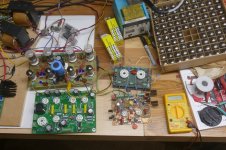
The first use of UNSET / CSD technology was in a push pull amp. That little amp is shown next to a Tubelab board for size comparison. The SPP makes 15 to 20 WPC. The push pull CED based amp makes 70 to 80 WPC!
The original breadboard for the CED is the green perf board seen to the right of the completed and operational push pull amp. It is being driven by a hacked up driver board that I never released. You can see the flying feedback resistors in the spring wire connectors around the perimeter of the perf board. The grid to ground resistors look like 100 ohm resistors in the picture, but they are really 20K. The orange bands are brownish due to some abuse, but theparts are still good.
I have not had the time to go back to this breadboard for more testing.
Attachments
You are right, it wasn't clear: I was talking about the driver tube feeding the output stage, that indeed is few pF of Crss. Thanks.Not sure if you are referring to the source driving the UNSET board, or the driver tube feeding the output stage, but the response is similar. Each is looking into R102 or R112 (1 meg) in parallel with the Crss of the mosfet (pretty small). Unless the driving impedance (Zout) is quite large the loading effect of the next stage is minimal.
This opens the road to driving impedances up to 100k (something more depending on the pmsofet), so to other opportunities and configurations.
Or will it be less due to the dV/dt capability of the current flowing through the driver?
I'm indeed simulating in the last weeks some PP amps with this configuration on the poweramp, giving very good results and very high power. They seem to be very very interesting and able to get around twice the normal power without exceeding the specs of the tube. I will post them after the first amp will be built, and I can share the schematics with you in pvt if you are interested into.The first use of UNSET / CSD technology was in a push pull amp. That little amp is shown next to a Tubelab board for size comparison. The SPP makes 15 to 20 WPC. The push pull CED based amp makes 70 to 80 WPC!
I have been using the C-14x choke in my UNSET since I first fired it up and have not thought about it's 200mA rating since. Well now after all the changes my DMM tells me I am pushing just a bit over 250mA through it. Browsing around I see 300mA 5H chokes available that are big, expensive, and heavy. 300mA 2.5H chokes about the same size as the C-14x and about 1/3 price of the 5H choke but less filtering. Any other options to consider?I realized today that the choke I am using is rated for 200mA. It is the Triad C-14x. With the output tubes biased at 80mA that puts me at 160mA plus whatever is going across the input tubes. Should I be looking for something that can handle more current?
I replaced the little choke in my UNSET test setup when I noticed that it was too hot to touch after a few hours of playing music. The current choke is a Triad C-17x which is 1.5H @ 300 Ma. I don't hear any hum, but I am using 87 dB speakers with limited LF response. If I find another one in my stuff, I'll try two in series to see if it affects the measurements. The C-17x barely gets warm and I'm probably at or slightly over 300 mA. The 250 mA PT gets a bit toasty, but that's normal for a Hammond even with minimal load.I have been using the C-14x choke in my UNSET since I first fired it up and have not thought about it's 200mA rating since. Well now after all the changes my DMM tells me I am pushing just a bit over 250mA through it. Browsing around I see 300mA 5H chokes available that are big, expensive, and heavy. 300mA 2.5H chokes about the same size as the C-14x and about 1/3 price of the 5H choke but less filtering. Any other options to consider?
For the next 10 days the bench will be dark, it's hamfest time. If I find a few spare hours I need to try some 4D32's in the UNSET. They are already in the "sell" pile, but I'm having second thoughts.
I saw the Triad C-17x and also the Hammond 159L which is a 2.5H 300mA choke as options that are around the same size and price as the C-14x. Maybe I'll give the Hammond a go and see if it does the job.I replaced the little choke in my UNSET test setup when I noticed that it was too hot to touch after a few hours of playing music. The current choke is a Triad C-17x which is 1.5H @ 300 Ma. I don't hear any hum, but I am using 87 dB speakers with limited LF response. If I find another one in my stuff, I'll try two in series to see if it affects the measurements. The C-17x barely gets warm and I'm probably at or slightly over 300 mA. The 250 mA PT gets a bit toasty, but that's normal for a Hammond even with minimal load.
For the next 10 days the bench will be dark, it's hamfest time. If I find a few spare hours I need to try some 4D32's in the UNSET. They are already in the "sell" pile, but I'm having second thoughts.
I got a little silly today and now have 4 100uF motor run caps in place for C2 and a 50uF motor run cap in place of C1. Along with this I hooked up a Pass B1 buffer to see how that works to drive the UNSET since I am still deciding if I want to use a preamp or go integrated. Just complicating my life at this point since it is sounding very good.
As a test I ran the amp for a couple hours and checked the Triad C-14x choke, it was very hot. This choke is definitely not up to the task with 250mA passing through it. I ended up finding a Hammond 193L to try, bigger and heavier than I wanted but it was available for just a little more than a 159L and the seller could get it to me quickly so I went for it. After hooking it up I re-ran the FFT tests.
1 Watt - Much the same as before

5 Watts - Again much the same as with the C-14x in place

10 Watts - Now I am seeing differences. H2 is more dominant with the 193L choke than with the C-14x. 10 watts is the point I have been focusing on as a measure of overall THD behavior so I like this result.

20 Watts - I skipped right past 18 watts where I measured previously because there was no point. 20 watts using the 193L choke looks better than 18 watts did with the C-14x choke. H2 is still dominant and distortion is at 1.5% THD. Before the amp was falling apart at 20 watts now I think you can easily call this a 20 watt amp.

After I ran the tests and let the voltage come down I put my hand on the 193L choke and it was not even warm.
1 Watt - Much the same as before
5 Watts - Again much the same as with the C-14x in place
10 Watts - Now I am seeing differences. H2 is more dominant with the 193L choke than with the C-14x. 10 watts is the point I have been focusing on as a measure of overall THD behavior so I like this result.
20 Watts - I skipped right past 18 watts where I measured previously because there was no point. 20 watts using the 193L choke looks better than 18 watts did with the C-14x choke. H2 is still dominant and distortion is at 1.5% THD. Before the amp was falling apart at 20 watts now I think you can easily call this a 20 watt amp.
After I ran the tests and let the voltage come down I put my hand on the 193L choke and it was not even warm.

I just remember that I did a simulation (need to find the file, it was on another laptop) with a LND150 DC coupled to a EL84 in UNSET, where the bias of the EL84 is set by adjusting the reference voltage of the bottom resistor of the FETSET. The LND150 was working at around 2 to 3mA IIRC. Numbers were really good. Like in the PP design, there was around 20% UL too.I don't have the same LND150 model that you have. [omissis] I managed to squeeze 300 V p-p out of it at -60 dB of H2 and -65 dB of H3 on 450 volts of B+ with a few tweaks.
The DAC I was using output a maximum of 1.5V. This was enough to drive the amp to 20W but with the current setup that is not max output. I swapped in a DAC that will do 2V out and was able to see 23.5W as the amp went into clipping.
And here I thought the UNSET would be an end game amp for me So do I need to start collecting parts for a FETSET amp now? 🤔I just remember that I did a simulation (need to find the file, it was on another laptop) with a LND150 DC coupled to a EL84 in UNSET, where the bias of the EL84 is set by adjusting the reference voltage of the bottom resistor of the FETSET. The LND150 was working at around 2 to 3mA IIRC. Numbers were really good. Like in the PP design, there was around 20% UL too.
I hope not to hijack the thread, but this is the sketch I was talking about, for the DC-coupled FETSET-UNSET amp.

Everything needs to be deeply optimized, but still gives something more than 7Wrms and 0,4% THD at 1Wrms.
Everything needs to be deeply optimized, but still gives something more than 7Wrms and 0,4% THD at 1Wrms.
Heads up to anyone looking for CCS regulator chips. Mouser shows 358 IXCP10M90S in stock as of today.
I currently have all motor run caps in place for C1 and C2. They are rated for 440VAC and from what I understand should be more than safe for 500VDC. For C1 I could not tell any difference between the motor run and electrolytic caps so would like to go back to the electrolytic to save some space. In fact with the new choke in place I may revisit C2 as well. However when I start the amp these caps see up to a 506VDC spike before B+ settles down into the 430VDC range. If I plug the 500VDC caps back in am I risking early failure?
What brand C1 do you have? Check the specs. A reputable manufactured cap will probably be Ok with a small 6V spike over spec. The Kemet ALC40 series spec sheet for example says a 550Vdc surge on a 500 Vdc cap is permissible if “ ≤ 30s Surge followed by a no load period of 330s, 1,000 cycles at +85°C” https://www.mouser.com/datasheet/2/212/KEM_A4026_ALC40-1101521.pdf
Have you considered an inrush current limiter? That should take care of that small overvoltage. I will use a CL-60 (or two) in the primary of my power transformer. https://www.mouser.com/ProductDetail/Amphenol-Advanced-Sensors/CL-60?qs=w3gjcs3NwciEQjXGFRAAAA==
Have you considered an inrush current limiter? That should take care of that small overvoltage. I will use a CL-60 (or two) in the primary of my power transformer. https://www.mouser.com/ProductDetail/Amphenol-Advanced-Sensors/CL-60?qs=w3gjcs3NwciEQjXGFRAAAA==
- Home
- More Vendors...
- Tubelab
- UNSET Beta Board Build