Measured across R7 I see 348V and 305V so about 6.3mA total current in this setup. I have been thinking the same, that the driver tubes can use more current which is why I decreased the value of R108/208 and one of the reasons I wanted to try bigger output tubes and more bias current. Interestingly one other test I did was to lower the plate voltage way down on the driver tubes with the thought that this is another way to get more current. At 1W around 60V 3H becomes dominant but then around 50V 2H comes back up. Setup like this 2H remains slightly dominant all the way to clipping. However if I adjust both channels to 50V the amp becomes unstable somewhere around 5-6W.
spiggs,
Your new operating point and results are impressive; 17 watts at 5% THD, at 1 kHz with plate dissipation under 40 watts! Wonder what power and THD is a available at a 30 Hz. Also noteworthy that the loss in output power with the higher impedance load does not buy you much in reduced THD.
Getting back to the plate voltage on the drivers, thanks for checking. We are loosing over 40V across R7 when a higher supply voltage might be beneficial. I am going to take out R7 in my PCB and try a small ckoke instead- I have a cute little 20 ma, 10H can IIRC, close in specs to a Hammond 153E. With under a 1000 Ohm resistance the voltage drop should be a considerably less, and further improve the smoothing of the driver supply.
At 6.3/2 ma you are dropping 315 V across the driver load 100k resistor (R108). That leaves a plate voltage on the 12GN7a of -10V 😳 I guess the screen current is significant. What is the actual plate voltage on the 12GN7a (pin 7)?
Last edited:
30Hz test tone shows 1% THD at 1W and 5% THD at 8.5W. With 400V B+ I see 7.7mA of current and pin 7 measures 6.7V.spiggs,
Your new operating point and results are impressive; 17 watts at 5% THD, at 1 kHz with plate dissipation under 40 watts! Wonder what power and THD is a available at a 30 Hz. Also noteworthy that the loss in output power with the higher impedance load does not buy you much in reduced THD.
Getting back to the plate voltage on the drivers, thanks for checking. We are loosing over 40V across R7 when a higher supply voltage might be beneficial. I am going to take out R7 in my PCB and try a small ckoke instead- I have a cute little 20 ma, 10H can IIRC, close in specs to a Hammond 153E. With under a 1000 Ohm resistance the voltage drop should be a considerably less, and further improve the smoothing of the driver supply.
At 6.3/2 ma you are dropping 315 V across the driver load 100k resistor (R108). That leaves a plate voltage on the 12GN7a of -10V 😳 I guess the screen current is significant. What is the actual plate voltage on the 12GN7a (pin 7)?
I tried dropping the value of R7 down to 5K previously but did not see much if any difference. I just tried dropping it down to 1.5K, 0.8K then 0.6K to see what would happen. At 0.6K THD at 1W does not change but it does have a little more bias to 2H and this continues through at higher outputs. Focusing on 2H If I adjust for about 0.55% THD at 1W by adusting the driver pots then 2H remains at least slightly dominate to 17W where it evens out at 2.1% THD 2H and 2.1% THD 3H. Higher orders are generally lower as well. Pin 7 is about 7.2V setup like this.
Hmmm! Pin 7 is the driver plate, right? And it shows 6.7 V? Is that in reference to ground or cathode, pin 2? Either way, something seems not right. Can the mighty 12GN7a work with only 6.7 volts across from plate to ground or even plate to cathode?
The 7.7 ma you mentioned, is 7.7 ma going through R7 that supplies two 12GN7as; both plate and screen current? Pete Millett’s test on the 12GN7 in pentode mode shows ~40 ma plate and 5 ma screen current at Vp=238 V and Vg2=150 V respectively. See http://www.pmillett.com/pentodes.htm
George, could we request your input on this? Help us to get to the bottom of this? What are the expected operating conditions for the UNSET beta board driver tubes especially 12GN7. What do you actually measure on your build with a 12gn7?
On a related matter, I’m interested to know why you chose Vg2=56 V (set by D4). Does that mean (in spriggs’ case) Vp=6.7 and Vg2=56V? Strange! I must have something wrong.
Last edited:
Correction and my apologies for being a dim bulb. Pin 7 measures 125V referenced to ground. This is the current setup running 400V B+ and a 600 ohm resistor for R7 with it dialed into 0.55% THD at 1W for more 2H throughout the power spectrum.
spiggs,
Thanks for this information; no apologies necessary. So, now we can calculate the 12GN7 plate current is (400-125)/100k = 2.75 ma. 7.7 ma total for plate plus screen current for the two driver tubes makes sense now. But very low. I have difficulty assessing the loadline because it is real close to the bottom of the graph. https://frank.pocnet.net/sheets/135/1/12GN7A.pdf
I hope George would discuss the details and rationale of the operating point for the driver tube. But the proof of the pudding is in the eating, and it sounds like you are enjoying your UNSET.
Last edited:
I am enjoying the UNSET. After a weekend of tweaking and listening this is my favorite configuration so far. R7 is at 600 ohm now and I settled on 100V of plate current and 100mA bias on the output tubes. THD at 1W is around 0.55% like this and 2H remains at least slightly dominant to 17W. I still of course can dial in lower THD at 1W but for whatever reason this is where my ears like it best.
It will be interesting when George finally gets a chance to play around with the driver and output stages separately. I know one of the design parameters of the UNSET was to use a wide range of tubes and right now I can't use the 6EJ7 in mine anymore so with my changes I have violated at least one design goals.
Really looking forward to your build Francois, curious to see if your findings are similar to mine.
Hehe! Thanks for the nudge to get my UNSET operational.
I had hoped that George would find time to get his lab together again and do some tweaking to incorporate in the UNSET Beta build. But I think I’ll finish mine now using close to your final setup. Thank you sincerely for your tweaks and experiments - a valuable and interesting journey to lazy Beta builders like me 😀
My setup will feature a choke in place of R7; B+ ~400 Vac; use a 12GN7a driver (plate load 100k) and 26LW6 outputs at ~100ma with the 3k primary Toroidy outputs. I’m self-debating whether I should increase the screen voltage on the driver, by changing D4 zener, but will probably start with the 56V already soldered in.
Unfortunately I’m not REW savvy (yet) and my hearing sucks, so I don’t know if any of my further experimentation will yield observable improvements.
Last edited:
I think REW was well worth the effort and not too hard to get going. What was most interesting was that it confirmed for me that lowest distortion does not necessarily sound better to my ears. If you do want to get REW going with the UNSET one tip, don't have REW generate the test tone and send it back through the same sound card interface used to measure. All I got was uncontrolled oscillation and a smoking usb audio device every time I tried. What worked is using a separate DAC to feed the test tone to the amp.
I am on the fence right now on if I should put this in a case or wait till George is able to do his testing and really dig into the optimum setup. While I am happy with the sound I know that when George finds the secret recipe to get the best out of the various tubes I will have to take everything apart and change it.
I also have the board I setup for 6DQ5s just sitting along with a pair of 1500K OPTs and have 2 different setups in mind that I may try with it. I could add a tube rectifier and change back to the 6EJ7 driver tubes and try for a simple setup with the 6DQ5s that I could use in my office. Or the other option which I have no idea how or if it would work is run 2 6DQ5s in parallel per channel into the 1500K OPT and see what it does. Would this be feasible and if so worth the effort?
The other side of the coin is that you could build one to your liking, as tested & listened to; then build one doused with George's "Secret Sauce" he cooked up & compare. 😎
Might be interesting.
Might be interesting.
Well I figure either George will come up with some small tweaks that I could try on the same PCB or major mods that I'll need to build a new one for anyway, perhaps he will come out with a rev 2 Beta or the UNSET proper. For now I have 2 built UNSETs to play with so why sit and wait 🙂The other side of the coin is that you could build one to your liking, as tested & listened to; then build one doused with George's "Secret Sauce" he cooked up & compare. 😎
Might be interesting.
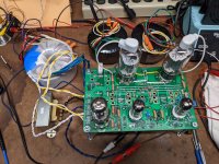
I decided to try out a tube rectifier with the 6DQ5s in combination with 6J51P drivers since I have a bunch of these and they are supposed to be a 6EJ7 equivalent. Really I had all the parts on hand so all it took was a little time at the bench. I am using a Antek AS-3T275 for power. These don't come with a 5V tap for the rectifier tube so I used some 18g wire to add one, it took about 15 turns to hit just a smidge over 5V under load. You can see my bodge under the blue tape, I'll use some good electrical tape to wrap it if I decide it should be permanent. B+ ended up at 340V. With these driver tubes changing the values of R108 and 208 did not seem to do much of anything, lowest value I could get away with was 125k but I just left it at 150k. Dropping the value for R7 did make an improvement. Overall 1W has 0.75% THD and 5% THD is at 10W. No listening yet.
Attachments
I wanted to listen to the UNSET with the 6DQ5, 6J51P, and tube rectifier but was too lazy to unhook the 26HU5 version and drag the speakers over to the other bench so I decided to try some headphones. Also if this were to replace my office amp it would would be optimal if it could do headphone duty as well as speakers. I had built a little headphone adapter for my SSE using an 8 ohm resistor across the speaker terminals and a couple of 120 ohm resistors in series to the headphone jack so I hooked that up. First thing I was reminded of is that a number of these 6J51P tubes I have tried have been a bit microphonic. One of the driver tubes gave just a hint of microphonics as background noise but it would settle down once I stopped fiddling with the setup. I have about 30 of these tubes so eventually I will sort through and set aside all the good sets for future use. Pity about world events and of course this is the least of it but these are old Soviet era tubes I purchased through a seller in the Ukraine for $1 each. In my testing they have been at least as good as the 6EJ7 tubes I have but I imagine they will not return to the market for a very long time if ever.
The UNSET sounded good through headphones. Besides the bit of microphonics the background was quiet and the music clear and dynamic. The sweet spot to my ears ended up being 100mA dialed in with the pots for the output bias and 100V dialed in to the plates of the driver tubes. Easy to remember.
One thing I would like to try is a little less B+. From testing with the adjustable regulator I always seemed to land on 325V B+ with the 6DQ5 tubes as the best setup. 340V isn't far off but is there an easy way to drop another 15V of B+ easily?
My setup will feature a choke in place of R7; B+ ~400 Vac; use a 12GN7a driver (plate load 100k) and 26LW6 outputs at ~100ma with the 3k primary Toroidy outputs. I’m self-debating whether I should increase the screen voltage on the driver, by changing D4 zener, but will probably start with the 56V already soldered in.
George,
Could you please comment on the rationale for the 56 V screen voltage used on the driver tubes? Would you recommend any changes to D4 to achieve a higher screen voltage (and as a result a higher current through the driver tube) for the “bigger” driver tubes such as the 12GN7a with plate dissipation of 11 watts? In spiggs’ setup it is dissipating only a small fraction of one watt.
Last edited:
Francois G I decided to try a 100V and 150V zener for D4 in the 26HU5 UNSET to see what would happen. I assume this is along the lines of what you were thinking. Screen voltage ended up at ~90V for the 100V zener and ~110V for the 150V zener. In both cases performance and stability was worse than with the 56V zener recommended in the BOM.George,
Could you please comment on the rationale for the 56 V screen voltage used on the driver tubes? Would you recommend any changes to D4 to achieve a higher screen voltage (and as a result a higher current through the driver tube) for the “bigger” driver tubes such as the 12GN7a with plate dissipation of 11 watts? In spiggs’ setup it is dissipating only a small fraction of one watt.
It is interesting that when adjusting the plate voltage of the driver tubes there is a balance between distortion, THD spectra, and stability. Lowering the voltage lowers the THD at 1W but this comes at the expense of 2H and eventually stability. For example I can get THD down to 0.4% at 1W but then 3H becomes dominant at 2W on up. I can get THD down to 0.18% at 1W but 3H is dominant and the amp becomes unstable at anything more than 5W of output. The sweet spot for me with the current setup has been around 0.55% THD at 1W. As the screen voltage increased with changes in D4 the window of adjustment became smaller, harder to dial in, and the plate voltage around which this centered became higher. Overall performance was slightly less. Maybe smaller changes in D4 could yield better results but I was thinking about the 12GN7A datasheet that shows a normal operating point for the screen voltage at 150V.
Guys, sorry for the prolonged absence, but a perfect storm of issues (parts shortages and personal issues, coupled with a phone call from my accountant to my wife) has kept my bench mostly idle for 2022. What little tube time I have has been spent testing alternate parts for use in place of the IXCP10M45S chip in the TSE-II and SSE boards. It seems that by the time I find something, get some here, test them and find proper parts changes to make them work, they are out of stock everywhere.George,
Could you please comment on the rationale for the 56 V screen voltage used on the driver tubes? Would you recommend any changes to D4 to achieve a higher screen voltage (and as a result a higher current through the driver tube) for the “bigger” driver tubes such as the 12GN7a with plate dissipation of 11 watts? In spiggs’ setup it is dissipating only a small fraction of one watt.
The operation of a pentode as a gain stage is a somewhat complicated interplay of several variables (primarily tube current, screen voltage, and load impedance) in a standard pentode configuration. I spent about a week with three or four pots in the circuit when optimizing a pentode for the input stage in a small high gain guitar amp. The UNSET is somewhat simpler in the respect that it will be used only in the linear (undistorted) region as opposed to operation from the linear through compressed and well into distortion region seen in a guitar amp. The CED ( UNSET ) mode adds a fourth major variable, the feedback resistor that is used to adjust the curves of the tube from pure pentode mode to emulated triode mode with lots of usable settings in between these extremes.
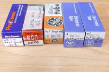
Early on I plotted tube curves for a few of the common tubes that could be used in the UNSET board. I also sent a box full of tubes to another forum member in Europe who makes LT spice models. The models and much of my testing turned out to be rather useless when I discovered that there are many different "things" that can be stuffed into glass and labeled with a tube type number. Often these "things" bear no resemblance to the type number on the glass or to each other. Of all the tube types that fit the UNSET board, I have more 6KT6's than any other types, so I started here. The pictures show 5 distinct things called 6KT6. I have since discovered two more. ALL behave differently in the UNSET board, and in the curve tracer. This led to the abandonment of the model making exercise and my simple optimization attempts. The 12GN7 is a relatively new video output tube, but I have already found three different things labeled 12GN7. One bears a striking resemblance to a 12BY7 and looks like one in the curve tracer. So it appears that there is no easy answer to making a common parts list for each tube type. Some optimization may be needed for each variety of a given type number, and amplifier power level (primarily due to available B+ voltage).
It is now known that attempting to optimize the board for several tube types is futile, so pick what you have and work from there. It appears that video output tubes like the 12GN7 may be the first choice, Sharp cutoff TV IF amp tubes like the 6EJ7, second and semi remote cutoff tubes like the 6EH7 the third choice.
Attempting to work with four variables at the same time leads to mistakes, maybe some blown parts, and possible insanity. The three pots in a guitar amp came close. Motorola sent us to yearly classes in Design Of Experiments and other useful stuff. The DOE classes made it clear that any useful experiment MUST consist of only one variable. That's possible and routinely done when you have an army of engineers and a nearly unlimited research budget. I like to fix one or two variables then play with the other two. Draw some conclusions, then change one of the fixed variables, perform the same experiment again, and iterate from there. Pick the best set of results and then change the fourth variable. sometimes you will still need to repeat the process a few times. We will start with a fixed feedback resistor and a fixed screen voltage. 56 volts was the best balance between total amp THD and gain in my experiments that attempted to work with several tube types. I now have a variable power supply connected into my board in place of the zener.
Francois G I decided to try a 100V and 150V zener for D4 in the 26HU5 UNSET to see what would happen. I assume this is along the lines of what you were thinking. Screen voltage ended up at ~90V for the 100V zener and ~110V for the 150V zener. In both cases performance and stability was worse than with the 56V zener recommended in the BOM......It is interesting that when adjusting the plate voltage of the driver tubes there is a balance between distortion, THD spectra, and stability. Lowering the voltage lowers the THD at 1W but this comes at the expense of 2H and eventually stability.
The fact that your screen voltage is not close to the zener voltage comes from two things (plate voltage and therefore screen current), The voltage probably varies as you adjust the tube current. This needs to be fixed before making any conclusions. For now we are considering the plate current (and therefore it's voltage) to be a variable, so the screen voltage must remain fixed. In any pentode the screen current depends on the plate voltage. As the plate voltage is lowered the screen grid will start to grab more of the electrons intended for the plate. This causes the screen current to increase and raises the distortion ( mostly 2H) because some of the plate current is being diverted to the screen. The zener and R8 should keep the screen voltage constant within a volt or two as the tube current (bias pot) is adjusted. Your screen voltage should be close to the zener voltage. It should be equal to the zener voltage with no tube in the socket. If the zener voltage itself goes down when the tube is installed the value of R8 should be decreased. This will cure most of the instability seen when the zener voltage starts moving with tube current. The grid bias is also derived from the zener so this voltage MUST remain constant or instability will be seen. R8 should be sized such that the zener diode operates at about 80% of its rated dissipation without driver tubes. The value in the parts list was chosen for a much higher B+ than used here. If the zener voltage still does not remain constant in operation a larger (dissipation) diode can be used. R109 and R209 can be used to limit screen dissipation if needed.
As seen the distortion is dependent on several things. So is the stage gain. we would like the distortion to be low, and with a good harmonic spectra. We also need enough gain to drive a big sweep tube to clipping from a common source like a CD player.
More in next post, hopefully tomorrow.
Attachments
Great information and input, thank you. I hope the “perfect storm” is over now at your place and you could find more peaceful time to experiment with the Beta board. Hopefully you will find the challenges interesting; we, the beta builders, certainly would love it.
I’m still working on digesting your discussion above, but this is good information and I’m looking forward to the next installment. My board is essentially populated now but I could easily make changes to D4 and/or R8 if you recommend it.
I’m still working on digesting your discussion above, but this is good information and I’m looking forward to the next installment. My board is essentially populated now but I could easily make changes to D4 and/or R8 if you recommend it.
Hi George, I saw that one of the contributors on this site, who also writes books, commented on one of your posts that you should write your own book. You really should! You have a way of making your thinking accessible, which enhances the outcomes you are describing. I think if your posts were all collated by topic, and compiled into a single volume, with a bit of context added, and diagrams where necessary, then you'd have created a new concept in tube literature.

That has been suggested several times in the past but collating and organizing all of my random disconnected thoughts has been an issue that I have struggled with all my life. At this point writing a book would take far more effort than possible. I have at least been attempting to collect and organize 15+ years of forum posts and other miscellaneous writings that I have created into like folders on my hard drive, but some have been lost forever. I did successfully publish one magazine article dealing with vacuum tubes and microprocessors that was published in 2009. I also wrote several defensive publications while working at Motorola. The magazine article was not well received in 2009 since those are essentially polar opposite technologies. I still have a microprocessor controlled high efficiency SE tube amp simmering away in my brain which is getting closer to reality (the OPTs arrived from Poland yesterday). It is based on the tech I published in the 13 year old article, which was derived from work on high efficiency RF power amplifiers used in cell towers.Hi George, I saw that one of the contributors on this site, who also writes books, commented on one of your posts that you should write your own book.
For now, let's discuss making a vacuum tube pentode amp work better in the UNSET board.
The pentode has a Gm (mutual conductance) associated with it. This is the change in plate CURRENT that is caused by a change in grid VOLTAGE. It is this Gm that creates voltage gain in a resistively loaded pentode. The changing current through the plate load resistor creates a changing voltage across that resistor. Most tubes, mosfets, and other devices that regulate current flow by a voltage control element have a number specified in a data sheet somewhere. This number might as well be a random number because it is only valid under the conditions imposed on the device when the measurement was made. Gm varies with the current through the device. Enclosed are the curves for a 6EJ7 and a 12GN7 since they are the most common tubes seen in the UNSET board. In the 6EJ7 data sheet the Gm curves are on the last page. There are slanted lines across the 5 individual plate curves showing the Gm. Each line represents a given Gm value. It can be seen that the Gm varies from 4000 around 2 mA to 22000 around 20 mA, and that for a given plate current, say 10 mA the Gm remains relatively constant as the plate and screen voltage is changed when the grid 1 voltage is adjusted to keep the current at 10 mA. The Gm is 16000 with 160 volts on plate and screen, but about 14000 with 240 volts on plate and screen. The bias must be changed from -1.9 volts to -3.2 volts to keep the tube current at 10 mA when the plate and screen voltages are increased. Most of this is due to the effect that the screen grid has on the plate current. Once a pentode is operating above the knee in the plate curves, the plate voltage has little effect on the plate current.
In a multi grid vacuum tube EACH individual grid in the tube has an effect on the plate current. G1, the control grid is closest to the cathode and has the greatest influence on tube current. G2, the screen grid has less control over plate current, and this amount of control is dependent on how close it is to the cathode, and how the grid wires are spaced. It is rare to find published values for the Gm of a screen grid in a common vacuum tube, but numbers in the 500 to 2000 range are typical. The suppressor grid (G3) has little control over plate current in a standard pentode, though some specialized tubes exist like the 6AS6 with a sensitive suppressor grid.
This shows us that the greatest influence on stage gain in a pentode amplifier are the Gm, which is directly dependent on tube current, and the plate load impedance, because the changing current through the tube gets turned into a changing voltage by the load impedance. A 1 mA change through a 1 K resistor will create a 1 volt change across that resistor. The same 1 mA change through a 10 K resistor will cause a 10 volt change, and that 1 mA through a 100 K resistor will cause a 100 volt change. This shows that making the load impedance as high as possible will greatly increase the gain, but making the load resistor bigger will also lower the plate voltage. There is a point where the plate voltage gets too low for the tube to operate without excessive distortion.
The tradeoff here is in the value of the plate load resistor. A large resistor will allow more gain, but results in a lower plate voltage. once the plate voltage gets low enough to cause distortion the only remedy is to lower the tube current to bring the voltage back up. Lowering the tube current will lower the Gm which reduces the stage gain. One can iterate back and forth between resistor value and tube current to find the best compromise between gain and distortion. At this point one can try a different screen voltage, then repeat the resistor - plate current dance to find out if changing the screen voltage made things better or worse. After finding the best combination of all three, then one could try a different feedback resistor and repeat the whole trip again. Obviously this can take some time and the results may be quite different with a different tube. I spent a dozen hours or so finding a happy spot for one of my 6KT6's only to find that it was not representative of the other 299 similar tubes.
It can be deduced that running the amp from a 500 volt supply gives a lot more headroom for the input stage compared to a 350 volt supply. This is true since you can use a large plate resistor and still get a good amount of plate voltage. There is another possibility.
We can shunt some additional current around the plate load resistor to make the tube happy. Years ago there were some "special diodes" called current regulator diodes, or current limiter diodes. They are in fact a depletion mosfet with the source and gate tied together. they faded from the scene many years ago, but have returned as LED current controllers. Unfortunately all the new generation parts are SMD and limited to about 160 volts. A Constant Current Source can be made from a depletion mode mosfet, or one could use the IXYS IXCP10M45S CCS chip If you can find them. A CCS is the ideal load for a triode, or a pentode used to emulate a triode ( the CED used in UNSET). I use a 10M45S load instead of the plate resistor in the input stage triode circuit that is used my TSE / TSE-II and SSE amp designs to bring out maximum gain at minimum distortion from a 12AT7 (SSE) or 5842/WE417A (TSE). I was about to wire one into my UNSET board when my workbench collapsed.
Attachments
Maybe an idea before its time? Now it makes total sense to maximise the efficiency of the device, with every unused watt saved being a triumph.
A few years ago, no one would have liked the idea of a car that has an engine that stops at traffic lights, but now it is normal. Why should an SE amp burn maximum energy when it has not seen an audio signal for 5 minutes?
Have you ever thought of crowdfunding as a means to enable you to focus on the new designs? Maybe even to be able to employ a sorcerer's apprentice, for the donke work ;-)
- Home
- More Vendors...
- Tubelab
- UNSET Beta Board Build