I have never blown one despite several screw-ups, but I have spares. I have blown at least one of every other semiconductor in that board, but I often go poking around in a live board. Any time you stick a 60 volt part in a 400+ volt circuit dead parts can happen for the simplest reasons. Digikey has over 1000 in stock, and there are several other parts that will work here, so other than the wait time for replacements, its probably a low risk unless you are constantly tinkering with the board.Glad you are in business again! Do you think it was a random event/accident, or should we stock up on those transistors?
The Dayton hamfest, which is no longer in Dayton. Many years ago large hamfests were common I went to two huge Florida hamfests and several smaller shows every year for 50+ years. There were two of the biggest in Florida on consecutive weekends. Miami died when the NFL put the Superbowl on the same weekend as the hamfest which drove the price of hotel rooms to $500 per night when the big game was held in Miami two years in a row. The Orlando show and the Daytona 500 NASCAR race have collided in time a few times, but there are about 80 miles between the two venues and plenty of hotel rooms in both places. Several small and medium hamfests still exist, but there are only two left that bring 20,000+ people, Dayton and Orlando. Neither have taken place for the past two years. HamCom in Dallas folded during the Covid lockout. Orlando happened in February, but a death in the family cancelled my trip at the last minute. If there are no issues, I will be driving west Thursday May 19 for setup day. Despite the name, the swap area draws lots of electronic stuff that's not ham radio specific. The rules state," Flea Market spaces are for the purpose of selling or trading amateur radio, electronic or related equipment or supplies." There is also a list of non permitted items that make sense, Guns, Porno, pirated software.....Which hamfest are you going to, George? Good luck!
https://hamvention.org/
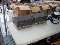
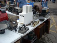
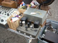
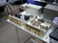
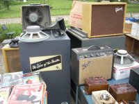
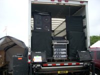
There are lots of strange sights at hamfests. The strangeness is somewhat different from say a computer show. The pictures show a few of them. Miss AntennaHead was a common fixture for several years. I can be found walking in the other direction on the left side of that picture. Someone is likely to be pickin something somewhere. You might even run into a NASA astronaut. Audio stuff in all sizes. Fishers come in two flavors, old and older. Speakers come in multiple sizes including large, and extra large. Sometimes things are cheaper by the truckload. Test equipment for $1 per pound.
I got a Mackie 32 channel mixing board with flight case for $75 at that show, and of course lots of tubes.
Attachments
-
 NEW-HAIRDO.jpg502.5 KB · Views: 170
 -
 Jammin_A.jpg151.1 KB · Views: 164
 -
 NASA_A.jpg169.1 KB · Views: 155
 -
 DSCN0872_x.jpg270.9 KB · Views: 150
 -
 DSCN0877_x.jpg296.1 KB · Views: 151
 -
 DSCN0883_x.jpg388 KB · Views: 154
 -
 DSCN0888_x.jpg324.8 KB · Views: 163
 -
 DSCN0891_x.jpg309 KB · Views: 158
 -
 DSCN0892_x.jpg348.6 KB · Views: 141
 -
 DSCN0904-x.jpg204.3 KB · Views: 156
 -
 DSCN0914_x.jpg332.5 KB · Views: 166
Last edited:
Thanks for the fun post and pics. I’ve never made it to one of these famous hamfests. I’m going to try this year. (As scheduled I will actually be driving through Dayton on my way to Alexandria VA on May 20th. I’ll try to spend the night and make the detour).
The hamfest is actually in Xenia, about 20 miles south of Dayton. Hotel rooms get rather scarce during the hamfest, so look now if you plan to stay in the Dayton area. I booked mine in November of 2021.Thanks for the fun post and pics. I’ve never made it to one of these famous hamfests. I’m going to try this year. (As scheduled I will actually be driving through Dayton on my way to Alexandria VA on May 20th. I’ll try to spend the night and make the detour).
I woke up the "Dayton Hamfest" thread this morning. There are a few other forum members planning to attend this year as well. This thread almost 200 posts with some useful info about what to expect.. There is a link to a video of an old show in post #110, and links in that video to 7 more like it.
https://www.diyaudio.com/community/threads/anyone-going-to-the-dayton-hamfest.165790/page-6
How would you implement a CCS in the UNSET for use with the driver tubes? Does the circuit just replace the plate load resister R108/208? Could I use something like this CCS pcb to experiment with? Should the resistors in the CCS circuit also be rated for 3W?I have been playing with LT spice simulations to find a happy spot for the UNSET input tube with a CCS chip or mosfet based CCS for the plate load as used in the SSE and TSE boards. This allows for a higher tube current and plate voltage.
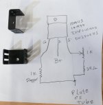
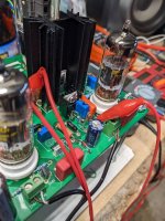
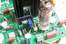
It looks like the board you referenced will work fine, but I didn't look too deep into it. The circuit is simple, so I just sky wired it. Schematic enclosed. I'll be leaving for church soon and have a Nerf gun war with the grandkids and their video game playing friends scheduled for the afternoon. My board is up on a shelf, but I'll try to get a picture of the CCS circuit this evening. The CCS chip needs to be heat sinked since it will eat a watt or two. I used a pair of the little guys shown in the picture placed back to back. I didn't use an insulator since I have been trying different parts. This puts B+ on the heat sink, so it's not recommended.
An ideal triode likes a pure CCS load. Neither of these exist in the real world. The 10M45 chip has somewhere around 1 megohm of impedance over the audio range in reality. Some triodes do not always work best into a near infinite load that a good CCS can provide so I stuck a large value resistor (1 MEG I think) in my board in place of R108 / R208 and wired my CCS on top of that. I did this partially for ease of experimentation, so I have not yet tried the CCS by itself.
You would need a 10M45 chip or a DEPLETION mode mosfet like the DN2540 or the IXTP01N100D and two resistors, a 1K gate stopper resistor and a current programming resistor in series with the source. Typical values range from a few ohms to a few hundred ohms depending on the CCS chip or mosfet being used. A 330 ohm resistor with a 10M45 chip gives 8 to 12 mA. Both resistors can be 1/4 watt since most of the dissipation will be in the chip or mosfet. I used a 1 K trimpot in series with a 39 ohm resistor in my experiments.
Attachments
Thanks, George. I was waiting for this guidance. When installed, what is your best guess wrt current we set for the CCS? spiggs and I are both using the 12GN7A driver tube.
Good luck with your NERF gun battle.
Good luck with your NERF gun battle.
Last edited:
Nerf gun battle with the grand kids sounds like a lot of fun 🙂It looks like the board you referenced will work fine, but I didn't look too deep into it. The circuit is simple, so I just sky wired it. Schematic enclosed. I'll be leaving for church soon and have a Nerf gun war with the grandkids and their video game playing friends scheduled for the afternoon. My board is up on a shelf, but I'll try to get a picture of the CCS circuit this evening. The CCS chip needs to be heat sinked since it will eat a watt or two. I used a pair of the little guys shown in the picture placed back to back. I didn't use an insulator since I have been trying different parts. This puts B+ on the heat sink, so it's not recommended.
An ideal triode likes a pure CCS load. Neither of these exist in the real world. The 10M45 chip has somewhere around 1 megohm of impedance over the audio range in reality. Some triodes do not always work best into a near infinite load that a good CCS can provide so I stuck a large value resistor (1 MEG I think) in my board in place of R108 / R208 and wired my CCS on top of that. I did this partially for ease of experimentation, so I have not yet tried the CCS by itself.
You would need a 10M45 chip or a DEPLETION mode mosfet like the DN2540 or the IXTP01N100D and two resistors, a 1K gate stopper resistor and a current programming resistor in series with the source. Typical values range from a few ohms to a few hundred ohms depending on the CCS chip or mosfet being used. A 330 ohm resistor with a 10M45 chip gives 8 to 12 mA. Both resistors can be 1/4 watt since most of the dissipation will be in the chip or mosfet. I used a 1 K trimpot in series with a 39 ohm resistor in my experiments.
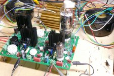
Although I did order some of those CCS boards (and will have extras if anyone is interested) being impatient I went ahead and wired something together for now. Did I get it right? Chip is a 10M45 (from Ebay!) and my pot is 470ohm with a 47ohm resistor in series since this is what I had, gate stopper is 1K. No smoke or explosions when I hit the power. Early indications seem to show a little improvement but real testing will need to wait till the electric company is done with some repair work. Power went out on Friday at 1am and stayed out till around 7pm. Crews where out all day replacing underground transformers and cables up and down the street but in the end brought in a generator and parked it in front of my house to provide power until they could get back Monday or Tuesday to finish. As a consequence where I was seeing 465V at C1 and regulating it down to 425V of B+ now I see 418V of B+ unregulated. We will see what happens when everything is back online.
Attachments
I did a little more testing with the CCS this evening since I was getting a measured B+ of 425V which is comparable to my setup prior to the electrical issues in my neighborhood. Gain is less with the CCS in place but I can still easily drive it to clipping with just a DAC as the source. Driver plate voltage wants to be higher, I have it set at 210V vs around 110V without the CCS. I am seeing about 0.45% THD at 1W, a 0.1% improvement. My benchmark has been to adjust the amp to have at least slightly dominant 2H up through clipping. 9V of output is a good reference since this is where the amp has the highest 3H relative to 2H. Getting 2H to equal or slightly exceed 3H at 9V results in dominant 2H throughout and a nice profile at 1W.
I got the UNSET board off the shelf and attempted to fire it up with several issues. I had been messing with the right channel driver circuit when it got shelved, which was dead when I powered it up. Some parts were lifted and the CCS circuit was dead, so I made two new ones and resoldered the parts that had one end lifted. The new CCSs used IXCP10M45S chips with a 1K pot, 1K gate stopper, and a 47 ohm max current resistor. Both were set at 10 mA with a power supply and DVM before installation and not touched after install. I popped in a 12GN7 and a 25HU5, set the output tube bias at 125 mA, and attempted to test with poor results. The THD was gross at about 5% at low levels due to lots of 60 Hz (not 120 Hz) sawtooth ripple. This turned out to be from my trusty old Fluke 407D power supply which is still all original. I guess it won't be for long. Rebuild time.
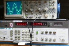
I swapped in my old Knight Kit supply which only goes to 400 volts, so that's where I tested (400 volts B+, 125 mA in the output tube, 10 mA in the driver, 1500 ohm load). I cranked the power up to 10 watts and turned R204 for best THD at 10 watts. With a constant 10 mA, R204 now sets the plate voltage. The THD at 10 watts remains below 1% for plate voltages between about 185 volts and 300 volts. Testing was done at 250 volts. My FFT analyzer is still not functional as turning the PC on without connecting it to the amp drives the THD floor up over 1%.
I got the following results.
Power THD
100 mW 0.144%
500 mW 0.183%
1 W 0.242%
2 W 0.333%
5 W 0.507%
10 W 0.944%
15 W 1.27%
18 W 1.32%
20 W 2.09% with visible clipping.
At 20 watts output the driver is putting out 28V RMS @ 0.228% THD
During the testing of a box full of 5842 tubes in a TSE-II board I noticed that most of the 5842's will make better THD on a reduced heater voltage. I plan to try this experiment on the UNSET board with the 12GN7's and other driver tubes.
Attachments

125mA is much higher than I have been testing at. How many watts are they dissapating in your setup? I have been setting mine around 90-94mA depending on B+.... I tested (400 volts B+, 125 mA in the output tube, 10 mA in the driver, 1500 ohm load)...
B+ is set at 400 volts. The plate of the 26HU5 is at 393 volts due to loss in the OPT. The cathode is 65 volts at idle, so there is 328 volts across the tube. At 125 mA there is 41 watts dissipated in the tube. One or two are dissipated in the screen grid so the plate is burning 39 or 40 watts. The 26HU5 is rated for 33 watts, but its plate is exactly the same size as some 26LW6's that I have and they are rated for 40 watts. Is 40 watts too much for a 26HU5? I don't know, these don't show red until well past 50 watts, but I'll eventually find out. I do have quite a few and I got them pretty cheap before Stan passed. I could have gotten many more at the time, but I thought that I would get them the next time I was in Florida.
I tinkered with my UNSET board all day yesterday and came up with some conclusions. Late last night I discovered that my driver tube screen voltage was dropping below 56 volts with some tubes, so I am repeating many of the measurements today. I have tinkered with all of the major variables that I mentioned before, and a couple that I have not yet discussed. As usual there are tradeoff's involved. The biggie now is distortion performance VS input sensitivity.
I ran through a handful of different driver tubes and found that most of the small ones (6JD6, 6JC6, 6KT6, and 6EJ7) like 7 to 10 mA in the CCS, while the larger tubes (12GN7, 12BY7, and 6HB6) like 10 to 15 mA. All seem to be similar in THD performance, but the overall gain is somewhat different from tube to tube. I need to retest once I change R7 and R8.
Each tube in the UNSET has local feedback applied to make the pentode work like a triode. It is also possible to apply a small amount of feedback from the output tube plate to the driver tube's grid. This does not involve the OPT so the usual GNFB stability issues do not apply. Using this technique it is possible to reduce the THD to impossibly small numbers at the expense of input sensitivity. How low can you go? How about 0.070% THD at 1 watt, 0.344% at 10 watts, and 2.10% at 20 watts (onset of clipping). With this much feedback it takes 2.8 Vrms at the input to get 20 watts out. Note that I have not actually listened to the amp configuration either, and I believe that it IS too much feedback.
My last experiment involved reducing the value of R213 to 15K reducing the feedback applied in the output circuit. This also changes the distribution of the DC voltage in the output circuit which allows for higher power output for a given B+ voltage. I also opened up the Kinght Kit power supply and tweaked it to give me 450 volts at full throttle to use this to my advantage. I reduced the output tube current to 100 mA and began to tinker some more with 450 volts of B+. That's when I discovered the screen voltage wandering in the driver circuit.
The weather today is conducive to more experimentation, so I should have more info later tonight or tomorrow.
I tinkered with my UNSET as well but all i managed to do was kill it :-( I can no longer adjust the right channel driver plate voltage. It just sits around 107V and the pot R204 does nothing. Left channel adjusts fine. I also noticed the screen voltage is about half what it was ~22V vs ~55V before on both tubes. I tried replacing Q201 and R204 but no change. I also took out the CCS circuit and just put resistors back in but no change. I think this is a result of a slip with the probe I use for grounding the DVM on the right side of the PCB off one of the small caps but I can't see anything obviously fried.
The most logical explanation for this would be a shorted C202. This is also where I have my ground clip attached so it is possible that the cap is cracked or otherwise physically damaged. Measure across it with an ohmmeter while turning pot R204. The reading should change while turning the pot. If constantly zero, the cap is shorted. Note that the cap is connected to the pot wiper, so a zero reading is normal if the pot is at the grounded extreme.
If this doesn't help, make the following measurements. Do any voltages on the tube (cathode, control or screen grid change when turning the pot? If not, what are the voltage readings? Does the screen voltage on the adjustable tube return to normal if the tube in the defective channel is removed?
If this doesn't help, make the following measurements. Do any voltages on the tube (cathode, control or screen grid change when turning the pot? If not, what are the voltage readings? Does the screen voltage on the adjustable tube return to normal if the tube in the defective channel is removed?
I have made some more mods to my board and have settled on a setup that I would like to try on both channels. I am currently modding the second channel. If it works out, I'll report the results, then cobble together a suitable power supply and make a temporary test amp. I want to listen to this setup for a few days at least. I liked my previous iteration of the UNSET board listening wise even better than a TSE-II with (cheap) 300B's. This iteration measures better than the one I listened to for nearly a year, but I haven't heard it at all, much less through good speakers.
I currently have 3 sets of parts values with measured data. All run 450 volts of B+ and an output tube current of 100 to 105 mA. The data set with the best numbers isn't sensitive for my (or most builders) use, needing 1.75 Vrms of drive to make 20 watts. My current favorite needs 1.2 volts to hit 20 watts where it makes 1.14% THD. It eases gently into clipping near 25 watts where it makes 2.67% THD, and clips pretty hard at 30 watts where it makes 6.05% THD. It leaves pure class A at around 20 watts as evidenced by the current meter on the power supply which starts to climb. At 30 watts my output tube current is about 250 mA. Exactly how this will sound, I don't yet know, but I bet it will be cleaner than abrupt clipping at 20 watts. Call it headroom for transients......if it handles transients properly.
I currently have 3 sets of parts values with measured data. All run 450 volts of B+ and an output tube current of 100 to 105 mA. The data set with the best numbers isn't sensitive for my (or most builders) use, needing 1.75 Vrms of drive to make 20 watts. My current favorite needs 1.2 volts to hit 20 watts where it makes 1.14% THD. It eases gently into clipping near 25 watts where it makes 2.67% THD, and clips pretty hard at 30 watts where it makes 6.05% THD. It leaves pure class A at around 20 watts as evidenced by the current meter on the power supply which starts to climb. At 30 watts my output tube current is about 250 mA. Exactly how this will sound, I don't yet know, but I bet it will be cleaner than abrupt clipping at 20 watts. Call it headroom for transients......if it handles transients properly.

UH, it's dead! I cobbled together a simple power supply that made too much voltage, about 515 volts of B+, so I removed the expensive power transformer and replaced it with an Antek toroid. My B+ was still a bit high at 470 volts, but I decided to play with it. I had both channels driven to over 30 watts when there was a pop followed by deadness. Autopsy tomorrow.....maybe.
The reading did not change on c202 when adjusting the pot but it was not zero. Pulled it anyway and it tested good. Have not taken all the voltage reading yet but I did pull the driver tube in the bad channel and screen voltage returned to normal.The most logical explanation for this would be a shorted C202. This is also where I have my ground clip attached so it is possible that the cap is cracked or otherwise physically damaged. Measure across it with an ohmmeter while turning pot R204. The reading should change while turning the pot. If constantly zero, the cap is shorted. Note that the cap is connected to the pot wiper, so a zero reading is normal if the pot is at the grounded extreme.
If this doesn't help, make the following measurements. Do any voltages on the tube (cathode, control or screen grid change when turning the pot? If not, what are the voltage readings? Does the screen voltage on the adjustable tube return to normal if the tube in the defective channel is removed?
This implies that something is forcing that tube into nearly full conduction. Either the cathode is nearly zero volts (shorted Q201, broken ground on pot), or the control grid is too far positive (open or broken R205).I did pull the driver tube in the bad channel and screen voltage returned to normal.
Well still no joy. R205 tested good but Q201 tested bad so I changed out Q201 and now I am back to a constant 340V plate voltage that I cannot adjust. Heater glows. i measured each pin with the tube out and got the following.
1 - 22.9 - 32v changes with pot
2 - 10.2v
3 - 25.4 - 29v changes with pot
7 - 340v
8 - 99v
9 - 5.6 - 18v changes with pot
Note I have a 100v zener installed in d4.
1 - 22.9 - 32v changes with pot
2 - 10.2v
3 - 25.4 - 29v changes with pot
7 - 340v
8 - 99v
9 - 5.6 - 18v changes with pot
Note I have a 100v zener installed in d4.
Hi spiggs,
I’m puzzled why pins 1, 3 & 9 measure slightly differently. They should measure the same. No?
What happens with the driver tube installed?
I’m puzzled why pins 1, 3 & 9 measure slightly differently. They should measure the same. No?
What happens with the driver tube installed?
- Home
- More Vendors...
- Tubelab
- UNSET Beta Board Build