Glad you seem to be in good spirits and feeling reasonably well after treatments. Best wishes for great health ahead.
When running tests I noticed that THD would always go down at any output level when I turned up the bias on the output tubes. I was wondering if more current at a lower voltage would give better results so I added a regulator in place of the choke and did some testing at lower voltages. After spinning the pots around I landed on 325V B+, 85V across the driver plates, and 92mA (23watts calculated) on the output tubes. Attached is the FFT plot at 1W and 0.61% THD. 5% THD comes at 11.5 watts. A better result I think.

Up until now I have been using a pair of the Toroidy KT88SE OPTs. I think George is using KT88PSE for most of his testing and there was some discussion if these would be a better choice for the UNSET. Curiosity and impatience got the better of me so I got a set of KT88PSE to compare. Plugging them in place of the KT88SE and using the 4 ohm tap into an 8 ohm load for 3K I get the same results at 1W and 5% THD comes in at 12.5 watts. So overall the only difference I see so far is an additional watt of output using the KT88PSE wired for 3K.
Next I tried 8 ohm on the 8 ohm tap to use them at the advertised 1.5K load. Results were not good, THD was around 2% at 1W and 5% came at 7 watts. I tried some different B+ voltages, bias points, and driver screen settings but did not find an acceptable match. I might try some different driver tubes with this setup but so far it does not look promising.
So now I have an extra PS that will give over 450V B+ and a set of 1.5K OPTs that might not find a home in my current UNSET plus extra mosfets and diodes. George, do you have any more of the beta boards to sell? I might have to build another for use with some bigger tubes.
Thanks for sharing your experimentation, spiggs.
Is there a way with REW to test the distortion numbers on the driver independent of the output section? I noticed that the driver tube seemed to operate at relatively low voltage and current, well below recommended operating conditions for these pentodes, and I wonder if that is a significant contributor to the amp’s distortion.
Is there a way with REW to test the distortion numbers on the driver independent of the output section? I noticed that the driver tube seemed to operate at relatively low voltage and current, well below recommended operating conditions for these pentodes, and I wonder if that is a significant contributor to the amp’s distortion.
I don't know of a way to just test the driver stage alone with REW but I have tested 5 different driver tubes and they do seem to be the biggest contributor to distortion. Adjusting voltage at the plate and indirectly current gives a wide range THD readings. Also the difference between the lowest and highest distortion tubes is about 0.6% THD at 1W when they are adjusted for best performance.
More testing. I wanted to try some different driver tubes with the KT88PSE OPTs so plugged in a pair of 12GN7As. Using the 8 ohm taps at 8 ohm for 1.5K results were better but still poorer than any other setup. I then connected the 4 ohm taps to 8 ohm for a 3K load. Best results so far. In this config the driver tubes wanted more volts across the plate for lowest distortion. Interestingly 2 different ranges gave acceptable distortion at 1W, ~110V and ~160V. I went with 110V since this had the 2nd harmonic dominant while at 160V the 3rd was dominant at 1W. Now getting 0.45% THD at 1W and 5% at 13W. Think I will do some subjective testing and give this a listen for a while. This is with B+ at 325V and output tube bias 93mA.

I am leaving now for my third doctor visit in three days in three different cities, mostly routine stuff, but today I get about 30 stitches removed from both shoulders so I should be able to start throwing OPT's and power supplies around again soon. I can't get this new forum to work right on either of my phones, so I won't be able to post while sitting around idle in a waiting room. I'll bring a 7 year old iPAD with me, maybe I can get it to work.
I do have some information to offer though, maybe later tonight or tomorrow.
Something I noticed when I put my board back on the bench, I have swapped the 30K feedback resistors (R113 and R213) out with 33K's sometime ago and forgot to write it down. This lowers the distortion in the output tubes, but makes the drivers work harder.
Hope all goes well with the doctor's visits George and ypur recovery is fast and "mostly routine".
Take care.
Take care.
What is the best practice for the interface between the PCB and top cap wire? I am concerned that this is a potential failure point from fatigue as the wires flex when I swap out output tubes. Is it normal to put some sort of sleeve at the base of the wire so the bend is not concentrated at the base?
Currently playing with wiring the output tube heaters in series so I can supply them with the same 12V supply I am using for the driver tubes. Testing with a Mean Well LRS-100-12 PSU. Doesn't seem to have an issue starting up in the heater circuit and I can adjust the output to 12.6V easily. So far so good, curious if I will see anything different in the THD graphs.
Currently playing with wiring the output tube heaters in series so I can supply them with the same 12V supply I am using for the driver tubes. Testing with a Mean Well LRS-100-12 PSU. Doesn't seem to have an issue starting up in the heater circuit and I can adjust the output to 12.6V easily. So far so good, curious if I will see anything different in the THD graphs.

I don't know if it's best or not but I used test lead wire with silicone rubber jacket. It's the stuff used in meter test leads so made to stay flexible and not work harden. Plugged into the board with only a tiny gap between board and jacket that will fill with solder when soldered from the underside the jacket then sits on something solid and there doesn't seem to be any single point stress at the bottom when the cable is moved. It really is pretty flexible.
Last edited:
What is the best practice for the interface between the PCB and top cap wire? I am concerned that this is a potential failure point from fatigue as the wires flex when I swap out output tubes. Is it normal to put some sort of sleeve at the base of the wire so the bend is not concentrated at the base?
I’m using a solid 18ga wire “post” soldered in the hole. Then the stranded wire (to the top cap) soldered to the post and the joint covered in a couple of layers of shrink tube.
I don't know if it's best or not but I used test lead wire with silicone rubber jacket. It's the stuff used in meter test leads so made to stay flexible and not work harden. Plugged into the board with only a tiny gap between board and jacket that will fill with solder when soldered from the underside the jacket then sits on something solid and there doesn't seem to be any single point stress at the bottom when the cable is moved. It really is pretty flexible.
Thanks for the ideas.I’m using a solid 18ga wire “post” soldered in the hole. Then the stranded wire (to the top cap) soldered to the post and the joint covered in a couple of layers of shrink tube.
Thinking about
The source I am using has a bit of gain so I thought I would try lowering the plate resistor value and see what happens. First I should note I am back to the KT88SE OPTs since ultimately I want to have both a 4 and 8 ohm tap available in the final config. I adjusted the value of R108/208 by paralleling resistors with the 150K resistor mounted on the PCB starting with a combined value of 130K and moving down to 40K. As I lowered the value I could see that the THD at 1W would become more 2nd harmonic biased for the same total THD value as I adjusted the driver plate voltage using the pot. This also carried over at higher output levels so the point at which the amp would become 3rd harmonic dominant would increase. However the effect diminished as the resistor value became lower and adjusting the plate voltage became very unstable around 40K.
I ended up settling on a calculated value of 92K for R108/208 by paralleling 2 470K resistors with the 150K in place. Setup like this THD is 0.55% at 1W and 5% THD comes at 13W. Still using 12GN7A driver tubes and 6DQ5 outputs biased for a dissipation of around 22W. This is the best result I have had with the KT88SE OPTs.
...Lowering the plate resistor value brings the voltage back up, but reduces the gain....
The source I am using has a bit of gain so I thought I would try lowering the plate resistor value and see what happens. First I should note I am back to the KT88SE OPTs since ultimately I want to have both a 4 and 8 ohm tap available in the final config. I adjusted the value of R108/208 by paralleling resistors with the 150K resistor mounted on the PCB starting with a combined value of 130K and moving down to 40K. As I lowered the value I could see that the THD at 1W would become more 2nd harmonic biased for the same total THD value as I adjusted the driver plate voltage using the pot. This also carried over at higher output levels so the point at which the amp would become 3rd harmonic dominant would increase. However the effect diminished as the resistor value became lower and adjusting the plate voltage became very unstable around 40K.
I ended up settling on a calculated value of 92K for R108/208 by paralleling 2 470K resistors with the 150K in place. Setup like this THD is 0.55% at 1W and 5% THD comes at 13W. Still using 12GN7A driver tubes and 6DQ5 outputs biased for a dissipation of around 22W. This is the best result I have had with the KT88SE OPTs.
Very interesting experimentation and encouraging results. Thanks for posting. I know audio memory is not very reliable, but I wondered if the amp sounds different to you now. Is it enjoyable to listen to with ~0.5% distortion at 1 watt?
I’m in Florida for the next two months, so my UNSET building is on hold at the moment.
I’m in Florida for the next two months, so my UNSET building is on hold at the moment.
Overall I have found the amp more dynamic than my SSE and once I had the hum issues sorted found it very enjoyable to listen to. Honestly at that point if I had no capability to measure anything I would have continued with the build and been happy. Now that I have REW running I am enjoying chasing THD numbers and learning a little along the way. Hopefully this is useful to others as these are BETA builds. After each config change and measurements I try to listen for a few hours to the result and my criteria is that it should be at least as enjoyable to listen to as before. I would say it sounds better to my ears now at 0.5% THD at 1W than it did at 1.2% THD but it's not a huge change. I will also say that I can get the THD down further but it starts to sound a bit flat to me and this corresponds with the 3rd harmonic becoming almost as prominent as the 2nd at 1W. Maybe it's all in my head but for me it seems to lose some magic setup this way.
Thank you. Your observations of your listening sessions and what you hear is insightful will certainly help me focus when I can start doing the same. The comparison with your SSE is especially interesting. What output tube are you using in the SSE? And your experiments and ability to chart the results in REW had been very helpful to me and I’m sure other (+potential) builders, as well as dialing-in the UNSET design.
Good health and best wishes to you all in the New Year. I’m looking forward to a time when George will be well and moving the UNSET prototype along like his usual self.
Good health and best wishes to you all in the New Year. I’m looking forward to a time when George will be well and moving the UNSET prototype along like his usual self.
Thank you. Your observations of your listening sessions and what you hear is insightful will certainly help me focus when I can start doing the same. The comparison with your SSE is especially interesting. What output tube are you using in the SSE?...
My SSE is using EL34s in triode.
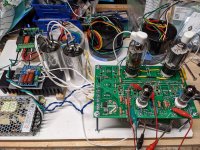
Spent the afternoon in the garage with the UNSET cranked up. Sounding toe tapping good in it's current config 🙂
Attachments
Well I managed to blow it up. I was testing different 6DQ5 output tubes to see what kind of variation I saw in THD between different constructions (~.1% THD at 1W) and suspect I plugged a tube in wrong. Fired up the amp, heaters on the output tubes did not glow, then saw smoke coming from Q1. Shut it down, pulled tubes and made sure they were in right, heaters now glow but bias adjustments not coming back in line and no sound. Bummer, well it looks like Mouser still has a few IXTP3N100D2 in stock, hopefully that's the only part that went.
Last edited:
- Home
- More Vendors...
- Tubelab
- UNSET Beta Board Build