I scale up or down to minimize on leading zeros, 0.1ohm = 100mohm, 0.22uF = 220nF
On schematics, I also use the scaler to replace the decimal point, as it can get lost or mis-read(poor print or photocopy), 0.1ohm = 0R10, 0.22uF =0u22F
So this is how one gets to 3K24. 3 significant digits usually means a precision R of 1% or better, using E96 series of values (96 values per decade)
Last edited:
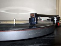
Realy true sound, incredible pure analog... Thanks everyone...
Really nice job, all of it.
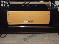
 I'm very impressed with Your case, and the fact, that You've also screened it for RF, gives an extra "+".
All the best
Ebbe
Thank you all for your help, ill now set about hunting for that resistor! And the capacitor values in the paralleled sections make sence to me now. I think the best thing for me to do is build the preamp first, test it and then look into my tube buffer circuit later...need to find a good valve to work on batteries! may have to bump the battery array up to 60 odd vaults.... but thats another story for another dqy...better keep on subject here...
Again, thank you for your help.
Again, thank you for your help.
Hi there ionian, may I ask where you purchased your capacitors and resistors?
Thanks in advance
Thanks in advance
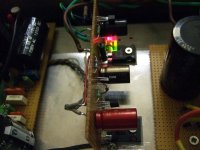
It is part art and part electronics = a thing of beauty, demonstrates, who needs an expensive pcb for a simple audio ckt.
Happy new year
Thank you rsavas.
Thank you very much Ebbe,Really nice job, all of it.
All the best
Ebbe
Yes, I have also screened it for RF with triple aluminium foil 🙂
Hi there ionian, may I ask where you purchased your capacitors and resistors?
Thanks in advance
Hello preludefan,
My part list:
A - Metal Film Resistors:
For one chanel! :
1 pcs 100 Ohm (100R) ...... : RN65D1000FB14 : Mouser
2 pcs 2.4 kOhms (2K4) ..... : RN65D2431FB14 : Mouser
1 or 3.24 kOhms (3K24)... : RN65D3241FB14 : Mouser
1 pcs 20 kOhms (20K) ...... : RN65D2002FB14 : Mouser
1 pcs 47 kOhms (47K) ...... : RN65D4702FB14 : Mouser )
1 pcs 100 kOhms (100K) ... : RN65D1003FB14 : Mouser
1 pcs 2200 kOhms (2M2) .. : HVR3700002204FR500 : Mouser
Total 8 pcs for one chanel
B - RIA film capasitors:
12pcs WIMA FKP Polypropylene 63V (33uF) %2,5 film cap ... ~20$ (30pcs for matching)
OR
12pcs MKP-1837 Metalized Polypropylene : partsconnexion.com
C - Output Cap:
2pcs 10uF Mundorf MCap %5 ................ ~16$
I changed to Mundorf MCap SUPREME 8,2uF...~90$ .... : Mundorf MCap SUPREME 8,2uF 600V High End Audio Kondensator | eBay
D - Electrolitic power cap:
2 Pcs 470uf 63V Elna Silmic II ............ ~12$
E - 2SK170 JFETs (quad matched):
4 Pcs Toshiba 2SK170-BL (6.8mA matched for my Goldnote Babele MM Cardige) ... ~4$ ...
Ask to seller for quad matched.
F - RCA phono jack:
4 pcs Switchcraft RCA Phono Connectors REAR MOUNT JACK ~10$ ... Mouser
G - On-Off Button:
1 pcs Metal Car Fog LED ON OFF Latching Switch 12V 16mm NICKEL-PLATED BRASS ~10$ ... :
H - RECHARGEABLE BATTERY:
20X NICD 2200MA Battery: 20x1,2V = 24V: ... ~50$
I- Intelligent Charger for NiMH NiCd 1.2V to 24V Battery Pack: ~25$
J- 24 AWG Solid High Purity Silver Plated Teflon : ~10$
thank you ionian! i was looking at the silver output caps myself, however these are a bit out of my price range at the moment and my system is only middle of the range as far as good systems go, so ill stick with the 10uf mcap for now... ill create my own thread when i havethe parts to start building it so you can all see what im up to... i still cant decide weather or not to use batteries, as i want to fit a tube buffer stage to it, but ill keep you informed!
would 3k3 do?
It is <2% high.
Does that 2% matter in this location?
If it does matter, then trim the 3k3 with a larger parallel resistor.
180k || 3k3 ~=3k2406 +- the tolerance of the 3k3.
Alternatively 3k0+240r = 3k24 +- tolerance of the 3k0.
It is <2% high.
Does that 2% matter in this location?
If it does matter, then trim the 3k3 with a larger parallel resistor.
180k || 3k3 ~=3k2406 +- the tolerance of the 3k3.
Alternatively 3k0+240r = 3k24 +- tolerance of the 3k0.
ok, i have built the circuit and tested it, wow! it sounds fantastic! however the gain is too low for my carts, can someone suggest a way to increase gain in this preamp if possible, if not, could someone suggest an lsk170 preamp to add some gain? i was looking at using tubes to do this at first, but i like the idea of using batteries!
thanks in advance, will post pics soon!
thanks in advance, will post pics soon!
I was about to start collecting parts for the elcheapo ... until I found this thread...
Mad_K writes on post 101 : :
so I thought, why not try cascoding from the start?
Salas, you replied in the following post with a schematic for DL110/160 (I am using the DL 110 myself, as the 160 is now discontinued), and asked Mad-k about his way of doing it.
I think I have gone through the whole thread twice without seen a schematic for Mad_K's cascoding version. Can someone help me here?
Salas, was the schematic you posted afters Mad_K's last post just a sim, or is it your working circuit? What do you think about the
I hope Salas or/and Mad_K still check this thread.
S.
Mad_K writes on post 101 : :
If I should redesign it today, I would probably go with 4 transistors/ch (2 fet + 2 bipolar in cascode)
so I thought, why not try cascoding from the start?
Salas, you replied in the following post with a schematic for DL110/160 (I am using the DL 110 myself, as the 160 is now discontinued), and asked Mad-k about his way of doing it.
I think I have gone through the whole thread twice without seen a schematic for Mad_K's cascoding version. Can someone help me here?
Salas, was the schematic you posted afters Mad_K's last post just a sim, or is it your working circuit? What do you think about the
that Thorsten mentions in the thread linked by Mad-K? Do you prefer the BC550 as per your schematic? (Thorsten gives a schem there using cascoding, but buffers too, which I don't want to use).good (Low Noise High Ft, High Beta, good Beta Linearity) NPN Transistors like BC239
I hope Salas or/and Mad_K still check this thread.
S.
Last edited:
Salas, you replied in the following post with a schematic for DL110/160 (I am using the DL 110 myself, as the 160 is now discontinued), and asked Mad-k about his way of doing it.
I think I have gone through the whole thread twice without seen a schematic for Mad_K's cascoding version. Can someone help me here?
Salas, was the schematic you posted afters Mad_K's last post just a sim, or is it your working circuit? What do you think about the that Thorsten mentions in the thread linked by Mad-K? Do you prefer the BC550 as per your schematic? (Thorsten gives a schem there using cascoding, but buffers too, which I don't want to use).
I hope Salas or/and Mad_K still check this thread.
S.
Now this must be the longest time cycle about an old post I had ever spanned. October 2008-March 2014. 🙂
-I was running a DL-160 at that time indeed. It was going through an early experimental Simplistic with resistive drain loads on both stages. That simulation was about showing Mad_K a both stages cascoded potential configuration to know if he had any comments on it since he was recommending an all stages cascode approach. That was post 111. He never answered, he never posted his own that he was talking about, he even never appeared again posting in the diyA forums I think. He must have had designed some kit with two 2SK170GR and six BC550C on 45dB gain named Atlantis MM. That is the historical account.
-The technical account is that after I continued my own experiments I did not like the cascoding on the second stage, I dropped it, and I changed the base bias scheme to JFET CCSed LEDs on the input stage. Made on matrix boards, It was very nice with the DL-160. I prefer BC550C and 2SC2240BL which is bit better. That progress is documented in my Simplistic thread in the older PDF guide that you can find linked from post#1 in that thread.
Since then it went through two major revisions and a PCB design to become the Folded Simplistic we know today. That old DL-160 companion mini box still lives today in a friend's system painted in KIA gold & augmented with a Partridge 977 SUT inside catering for a ZYX Bloom cartridge on a VPI Classic. Some nostalgia pictures are attached. 🙂
Attachments
Hi folks, so I thought I would try a cascode variant of the Le Pacific. Below is the schematic and picture of it assembled. I'm currently testing it and will post some screenshots of the oscilloscope.
Cheers
Dom


Cheers
Dom


Last edited:
Q6 and Q2 are not good for this circuit.
Q1 & Q6 form a cascoded common source amplifier. Similarly for Q4 & Q2.
To get good performance from the common source amplifier the Vds of Q1 and Q4 need to be >2*Vp (Read Borbely).
Lsk170 for Q6 and Q2 cannot get you sufficient cascode voltage to meet Borbely's voltage condition.
You should have a high Vp device for the cascode, not a low Vp device.
A low Vp device can usually be identified by very high gm.
A high Vp device can usually be identified by a low gm.
You need to select a low gm device, then measure the Vp.
Thanks AndrewT.
What volume would you recommend of Borbely? I went to his website and there are loads of volumes are there any in particular that are specific to cascode configurations in preamps?
Suprisingly it actually sounds pretty good at the moment. Not quite sure how if Q6 and Q2 cannot provide sufficent cascode voltage.
Measure Vds of the amplifier jFET.
It will almost certainly be less than 2*Vp. It will probably be less than 1*Vp.
The Vds of the amp jFET is also the Vgs of the cascode jFET.
High gm jFETs have a low Vp. An Id between Idss and 1uA (for Vp) results in a Vgs <Vp but greater than 0V
Borbely published a 2 part treatise on jFETs discussing their characteristics, how to test, how to select for duty, how to bias for good and very good performance.
It is worth reading all FET articles that Borbely released. They are gems worth remembering.
Hi,
Andrew's perfectly right.
A proven and really good combination are the 170 and a 4391 either in throughhole as 2N4391 or in SMD as MMBF4391 or SST4391.
The 4391 will give the 170 a drain source voltage of around 4-5V.
Also the 4391 are lownoise, low capacitance types, preserving the very lownoise character of the 170 and allows for high bandwidth.
For MM useage the 4391 and its little brethren 4392 and 4393 would already be low enough in noise.
jauu
Calvin
Measure Vds of the amplifier jFET.
It will almost certainly be less than 2*Vp. It will probably be less than 1*Vp.
The Vds of the amp jFET is also the Vgs of the cascode jFET.
High gm jFETs have a low Vp. An Id between Idss and 1uA (for Vp) results in a Vgs <Vp but greater than 0V
Borbely published a 2 part treatise on jFETs discussing their characteristics, how to test, how to select for duty, how to bias for good and very good performance.
It is worth reading all FET articles that Borbely released. They are gems worth remembering.
Those two parts by Borbely are indeed gems.
Hi,
Andrew's perfectly right.
A proven and really good combination are the 170 and a 4391 either in throughhole as 2N4391 or in SMD as MMBF4391 or SST4391.
The 4391 will give the 170 a drain source voltage of around 4-5V.
Also the 4391 are lownoise, low capacitance types, preserving the very lownoise character of the 170 and allows for high bandwidth.
For MM useage the 4391 and its little brethren 4392 and 4393 would already be low enough in noise.
jauu
Calvin
Calvin, thanks for your suggestion. I got some 4391 to try out. I placed the 4391 into the circuit. I noticed that the Idss of the 4391 is between 50mA and 150mA, my LSK170 has an Idss of 5mA. How do I calculate the new value for R8?
Thanks
Dom
Hi,
Andrew's perfectly right.
A proven and really good combination are the 170 and a 4391 either in throughhole as 2N4391 or in SMD as MMBF4391 or SST4391.
The 4391 will give the 170 a drain source voltage of around 4-5V.
Also the 4391 are lownoise, low capacitance types, preserving the very lownoise character of the 170 and allows for high bandwidth.
For MM useage the 4391 and its little brethren 4392 and 4393 would already be low enough in noise.
jauu
Calvin
Thank you for the precious info 🙂
Hi,
Andrew's perfectly right.
A proven and really good combination are the 170 and a 4391 either in throughhole as 2N4391 or in SMD as MMBF4391 or SST4391.
The 4391 will give the 170 a drain source voltage of around 4-5V.
Also the 4391 are lownoise, low capacitance types, preserving the very lownoise character of the 170 and allows for high bandwidth.
For MM useage the 4391 and its little brethren 4392 and 4393 would already be low enough in noise.
jauu
Calvin
Andrew
I have calculated the required resistance values for a common source LSK170B amplifier (See below) however when I introduce the 2SK246BL as a cascode how do I introduce this into the equations? Doesn't this reduce Id and therefore alter the required Rd and Rs resistance values? Should the Idss of the LSK170 (8mA) match the Idss of the cascode JFET (2SK246BL)?
Many thanks
Dom

Hi,
the current trough the Master JFET Q1 is still defined by its source resistor.
It'll be slightly lower than uncascoded, as its DrainSourcevoltage Vds will only be the GateSource voltage Vgs of the cascoding JFET.
To determine the Vgs see the Id-Vgs graph in the Datasheet and find the Vgs for the Id value of Q1 (5mA).
For the 4391 this will be around -4 to -5V.
This is more than sufficient for SK170.
Now the drain voltage of the cascoding JFET should be at leadt 2x its Vgs, hence > 8 to 10V.
The drain voltage equals the supply rail minus the drop over R5 and R8.
For Id=5mA these are 50mV and 15V, giving 10V.
The drop over R5 is negligible here as R5 is very small.
I'd increase R5 to 100R to improve its supply rejection.
The 500mA drop are till low enough.
jauu
Calvin
- Home
- Source & Line
- Analogue Source
- Ultrasimple MM/MC RIAA preamp 2