
But what does it sound like ?
very detailed and soft
clear highs and deep bass.
Hi Sajti
I took the Marantz sample
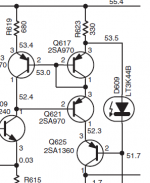
OK. My experience, that it sound even better if You connect the LEd to the emitter of Q621. In this case the impulse response is much better too.
Sajti
PCB rev 1.0
...... Ok,right now ,you have PCB , and Q.C. need to check this layout , this is my contribution ......🙂
Regards Alex.
...... Ok,right now ,you have PCB , and Q.C. need to check this layout , this is my contribution ......🙂
Regards Alex.
Attachments

Last edited:
Isn't the DC gain a bit high? And no input cap. I melted a speaker cone once with something like this.
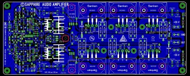
......have layout again , find some errors , corrected and revised 😉
Regards Alex.
Hi Alex
Very nice pcb layout. But I have a question. There are 8 transistors laying under the pcb, 8 transistors x 3 leads = 24 leads have to insert to the pcb before soldering. Is there any way to make sure it has no problem when inserting the leads through the pad holes?
I have designed some similiar pcb layouts but keep wondering if there will be any problem to insert the leads of transistors into the pad holes on the pcb.
Thanks
Hi SSDIY,
First you can insert , each transistor in position , solder each , and after mount pcb to the heatsink , ofcourse not so easy but with some skill you can do the job 😉 Thanks for kindnes .
Regards Alex.
First you can insert , each transistor in position , solder each , and after mount pcb to the heatsink , ofcourse not so easy but with some skill you can do the job 😉 Thanks for kindnes .
Regards Alex.
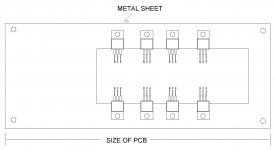
Solder just ONE lead of each output device. Maybe to just one side of the pad rather than all round.
This holds the transistors roughly, but not rigidly, in place.
Bolt or clamp to your heatsink.
Then when all is correctly aligned, re-solder that first lead to release any strain on that part soldered leadout.
Finally solder all the other leadouts.
This holds the transistors roughly, but not rigidly, in place.
Bolt or clamp to your heatsink.
Then when all is correctly aligned, re-solder that first lead to release any strain on that part soldered leadout.
Finally solder all the other leadouts.

This amp doesn't have safe operating area protection; short the output and you have one dead amp.
- Status
- Not open for further replies.
- Home
- Amplifiers
- Solid State
- ultra performance amp