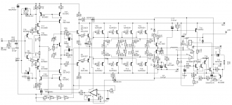
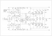
This is my amplifier, which use bjt input stage. 110W/8ohm output, with THD:0.0008% simulated.
And it contains the protection too.
Sajti
And it contains the protection too.
Sajti
Attachments
Last edited:
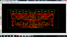
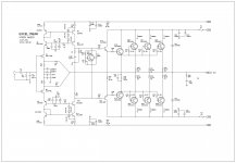
Very nice! 🙂....... @Karl vd Berg for you ,and not only ,here in attachment , it's an updated PCB, rev 1.5 .....🙂
Regards Alex.
The specs must outperform many stock amps??

Thanks for the offer but I don't have need of SOA limiters (if that's what you refer to) in domestic amplifiers. Perhaps I should say that I couldn't sell hi-fi amplifiers if I declared that they were fitted with any type of them. I would agree that PA and instrument amps such as I have also built in small numbers, do need limiters because the average output levels, operating stresses, abuse and risks are relatively much greater. I've been fitting dual and multislope SOA protection to these amps for quite some years because I have seen the damage caused by failures in them and the frequency with which it occurs. If your paper discusses something non-invasive and radically different in operating mode to dual or multislope limiters, I would be grateful to see it.
Actually, a properly designed SOA protection circuit should be inert when not invoked. Send me mail and I'll send you article on how to design them properly.
Yes.Actually, a properly designed SOA protection circuit should be inert when not invoked. Send me mail and I'll send you article on how to design them properly.
A properly designed IV limiter or SOA protection MUST allow all valid signals to pass to all valid loads.
If one has an 8ohms speaker as the load and that particular speaker demands 30Apk on very rare occasions, then the amplifier that is used with that speaker should allow that 30Apk to pass to the speaker without the limiting interfering with the quality of the signal.
Hi 400kg,
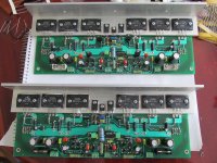
I see you are using 0,1R emitter resistors in the ops with three pairs of 2922/1216. I would like to use 0,1R or 0,15R for the same devices but with four pairs in parallel. With these values I can run the ops with 0,133 to 0,18bias current/device, this to achieve a nice class A output power.
But these values are looking rather small compared with other amp's using other output devices!?
Do you have any idea if the LAPT technology used in these Sanken devices are beter suited to use with rather low emitter resistors?
Any info is welcome!
Cordell did a piece on output device Thermal Stability.
Maybe the Cordell interviews - outputs Thread.
Maybe the Cordell interviews - outputs Thread.
Thanks for the hint Andrew! We mostly forget to check the available documentation.
Douglas Self goes relative far into detail concerning the emitter resistor value in an ops.
I'll start with a 0,1R and see if I get it thermally stable.
Greetz
Douglas Self goes relative far into detail concerning the emitter resistor value in an ops.
I'll start with a 0,1R and see if I get it thermally stable.
Greetz
The output transistor becomes less Thermally stable as Vce rises.
Cordell gives an arithmetic procedure to predict the onset of this unstable voltage. Basically, you need higher Re values for higher Vce in both BJTs and mosFETs.
Cordell gives an arithmetic procedure to predict the onset of this unstable voltage. Basically, you need higher Re values for higher Vce in both BJTs and mosFETs.
scope caps and problem
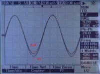
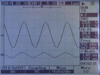
positive portion of the output wave is problematic. why is this happening?
positive portion of the output wave is problematic. why is this happening?
Attachments

Last edited:
Have you set your scope at DC or AC input signal? When set at DC is could be that you are seeing a DC-offset on the output?
Have you set your scope at DC or AC input signal? When set at DC is could be that you are seeing a DC-offset on the output?
Hi.My friend has made this measurements.The first picture is both ac as you can see on the top of oscilloscope screen. Amplifier's output is asymmetric.What can we do?
I am just thinking out loud:
An error like this should normally be corrected by feedback, so, could it be caused by something out of the loop? For example the VI-limiter?
The scope picture is with 26v output signal, do you have the same error with smaller output voltages?
Could you measure again without the limiter?
An error like this should normally be corrected by feedback, so, could it be caused by something out of the loop? For example the VI-limiter?
The scope picture is with 26v output signal, do you have the same error with smaller output voltages?
Could you measure again without the limiter?
..... Hmmm ,congrats as usual from you ,nice schematic , but have you built , or just simulated ?🙂 Off course a decent PCB it's needed .😉
Regards ,
Alex
Regards ,
Alex
- Status
- Not open for further replies.
- Home
- Amplifiers
- Solid State
- ultra performance amp