Hi Chris,
You're right, I use Multisim.
Cheers,
Valery
edit... Spice models for vacuum tubes?
Hi vzaichenko,
I use Multisim as you did, but I have difficulties simulating the circuit.
Can you share your multisim schematic files please? I have spent many days debuging it.
regards,
Erikovsky
I use Multisim as you did, but I have difficulties simulating the circuit.
Can you share your multisim schematic files please? I have spent many days debuging it.
regards,
Erikovsky
Hi vzaichenko,
I use Multisim as you did too, but I've got some difficulties. tried many days.
Can I share your multisim schematic files please? I got my own schematic, but with some lack of good transistor spice models , the simulation is bad 🙁
regards,
Erikovsky
I use Multisim as you did too, but I've got some difficulties. tried many days.
Can I share your multisim schematic files please? I got my own schematic, but with some lack of good transistor spice models , the simulation is bad 🙁
regards,
Erikovsky
What voltage range is recommended for the IPS power rails?
I was thinking of running the LatFET OPS at 50 -60V and usually the front end likes a few Volts more when powered separately.
I was thinking of running the LatFET OPS at 50 -60V and usually the front end likes a few Volts more when powered separately.
What voltage range is recommended for the IPS power rails?
I was thinking of running the LatFET OPS at 50 -60V and usually the front end likes a few Volts more when powered separately.
yes i have used it in similar fashion for the LatFETs. ALF16N20W and P.
They work like charm. You might find oscillation if powering more than one pair some times it does oscillate. The only thing is add some 100pf to between the gate and drain. Overall the sonic quality will be good just like hitachi laterals.
BTW, my plan is Tube+NS-OPS thanks a lot.
Hi, please drop me your email.
What voltage range is recommended for the IPS power rails?
I was thinking of running the LatFET OPS at 50 -60V and usually the front end likes a few Volts more when powered separately.
Hi Rich,
My build runs at +/-50V rails, although initial prototype was tested at +/-70V.
So, anything in the range you suggest (50-60V) will be fine.
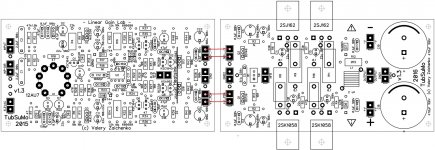
A few volts more for the front-end makes sense only if you really care about energy efficiency. Otherwise, you can connect the front-end rails right to the cap multipliers, located on the OPS board - see red lines on the picture.
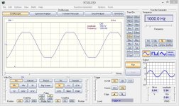
Clipping is perfect due to the special VAS topology (combination of Baxandal's super pair and Hawksford's cascode) - clean cut, no rail sticking whatsoever (picture is live measurement with +/-70V rails - digital oscilloscope). It clipped at 136V amplitude, meaning VAS took 2V on each side. Nothing to worry about.
Cheers,
Valery
Attachments
yes i have used it in similar fashion for the LatFETs. ALF16N20W and P.
They work like charm. You might find oscillation if powering more than one pair some times it does oscillate. The only thing is add some 100pf to between the gate and drain. Overall the sonic quality will be good just like hitachi laterals.
Hi rhythmsandy
In this design, if you use my layout, the gate-drain caps are not required (note the different gate stopper values for N and P channel FETs).
Those caps have to be used carefully, with proper testing at the spectrum analyzer. I experimented with them in N channel - starting from some value, they provoke a very harmonics-rich high-frequency artifacts.
Cheers,
Valery
edit... Spice models for vacuum tubes?
Please drop me your e-mail.
Hi Rich,
My build runs at +/-50V rails, although initial prototype was tested at +/-70V.
So, anything in the range you suggest (50-60V) will be fine.
A few volts more for the front-end makes sense only if you really care about energy efficiency. Otherwise, you can connect the front-end rails right to the cap multipliers, located on the OPS board - see red lines on the picture.
Clipping is perfect due to the special VAS topology (combination of Baxandal's super pair and Hawksford's cascode) - clean cut, no rail sticking whatsoever (picture is live measurement with +/-70V rails - digital oscilloscope). It clipped at 136V amplitude, meaning VAS took 2V on each side. Nothing to worry about.
Cheers,
Valery
Thank you Valery, I will run at 50V rails. I had the impression it would be nice to try a separate supply as your modular approach lends to this. But to do so would mean adding an off board cap multiplier circuit like on the OPS for front supply. Something to consider.
Earlier in the thread, I believe it could have been Jeff, found that matching R18 and R24 closely improved an offset problem. I have noted on the BOM that these should be 0.1% just in case.
Matched Renesas fets ordered and a pair of matched and balanced NOS Siemens tubes coming too. Within certain parameters there seems to a few drop in replacements for the 12AU7, one being the 12BH7A which I may try if I get the chance to find some.
I will very likely go for the Velleman scope you mentioned, It seems like it will get me started nicely. Thanks for the heads up.
Forgot to ask, would raising the output impedence from 2R2 to 10R have a detrimental effect on the performance? I have some nice 2W Kiwame resistors to use here.
Thank you Valery, I will run at 50V rails. I had the impression it would be nice to try a separate supply as your modular approach lends to this. But to do so would mean adding an off board cap multiplier circuit like on the OPS for front supply. Something to consider.
Earlier in the thread, I believe it could have been Jeff, found that matching R18 and R24 closely improved an offset problem. I have noted on the BOM that these should be 0.1% just in case.
Matched Renesas fets ordered and a pair of matched and balanced NOS Siemens tubes coming too. Within certain parameters there seems to a few drop in replacements for the 12AU7, one being the 12BH7A which I may try if I get the chance to find some.
I will very likely go for the Velleman scope you mentioned, It seems like it will get me started nicely. Thanks for the heads up.
Separate supply for the front end is possible - you can even use additional regulators for a "hi-end" build - but not really necessary. The front-end has got a good PSRR, cap multipliers on the OPS boards do the job - no hum, ripple, etc. Very low noise, if the ground is wired correctly.
R18 and R24 have to be the same in this kind of non-inverting DC servo topology - I use 1% tolerance resistors and don't have any problems. More important thing - remove the flux remains after soldering the boards and dry them well - servo operates with micro/nano currents and the flux remains conduct sometimes enough for introducing some error there.
I have bought 6 tubes from Electro-Harmonix (12AU7) - from those 6, 5 were very well-matched, 1 was rather unmatched. Good enough 🙂
Yes, Velleman combo is a handy tool, pc-controlled, precise enough.
Cheers,
Valery
Forgot to ask, would raising the output impedence from 2R2 to 10R have a detrimental effect on the performance? I have some nice 2W Kiwame resistors to use here.
Well, in fact, within an audio frequency range, the impedance of these parallel-connected coil and resistor is dominated by the coil - impedance of a piece of wire, rather low. Resistor value affects the Q-factor of the LC system, formed together with the speaker's capacitance, working in HF range. Having the resistor value too high may result in some possible unwanted resonance at HF, however, I don't think 10R will be really detrimental.
With my (extremely-prune-to-oscillation due to the type combos) OPS this resistor value was cruicial!
With 1-2R it was oscillating to 1-10nF capacitive load (some cable...) so around 8R it worked perfectly to any kind of C load.
With 1-2R it was oscillating to 1-10nF capacitive load (some cable...) so around 8R it worked perfectly to any kind of C load.
There is a slight discrepancy between the BOM and schematic.
The schem shows R41 / R44 (current limiting R's for drivers?) as 100R but BOM has them as 22R.
I take it the BOM is correct?
The schem shows R41 / R44 (current limiting R's for drivers?) as 100R but BOM has them as 22R.
I take it the BOM is correct?
There is a slight discrepancy between the BOM and schematic.
The schem shows R41 / R44 (current limiting R's for drivers?) as 100R but BOM has them as 22R.
I take it the BOM is correct?
Go by his latest schematic. He made some updates to improve stability.
Ok Jeff thanks.
I must have missed the explanation in the thread but I'm not sure what 'INP-DIR' is, certainly it isn't balanced (shame). Both inputs are decoupled the same so presume they are optional. I intended to only populate the C2 position.
I must have missed the explanation in the thread but I'm not sure what 'INP-DIR' is, certainly it isn't balanced (shame). Both inputs are decoupled the same so presume they are optional. I intended to only populate the C2 position.
Hi rhythmsandy
In this design, if you use my layout, the gate-drain caps are not required (note the different gate stopper values for N and P channel FETs).
Those caps have to be used carefully, with proper testing at the spectrum analyzer. I experimented with them in N channel - starting from some value, they provoke a very harmonics-rich high-frequency artifacts.
Cheers,
Valery
well the problem was when I use one pair of Alfets at the output things were stable but when you add more pairs they were becoming unstable.
- Home
- Amplifiers
- Solid State
- Ultra-high performance, yet rather simple - hybrid and more!