Hi Rich,
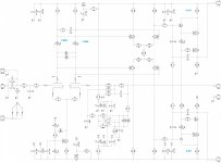
I assume, you've got the values as specified in version 1.3 for 50V rails (attached), right?
With regards to power-up procedure - it would be good to switch the tube heater supply (6.3V AC) 30-40 seconds prior to switching on the main rails.
Now - testing conditions. Input is shorted (not Inp-Dir, just normal Input). NFB, PD+ and ND- are connected together - this is your output for the time being.
Let's start with measuring the voltage across D3, D7 LEDs. It should be around 1.8V DC.
Then let's change R29 to 120R. Shorten D14, D15 LEDs, leaving only one LED in each shoulder (positive and negative).
Power it on and measure the voltage over R41, R44 (100R resistors).
All LEDs should be lit up except the ones you've shorted.
Cheers,
Valery
Test measurements on diagram below. I forgot to measure across D3 and D7 before changing R29.
R29 is 100R. D14, D15 LEDs are removed and shorted with wire.
Negative VAS LED still doesn't light up unfortunately unless I short NFB to GND. It stays dark through the whole start up, before, it would light then fade. Interestingly D3/D7 light immediately now whereas before they would begin after a few seconds.
if the voltage across R44 is greater does this mean the negative VAS rail is sinking less current? R41 = 113mV and R44 = 304mV. Both boards are identical in measurements and behaviour. So possibly I have made the same resistor value error on both?
Could try two LED's on the neg VAS?
Attachments
Last edited:
Test measurements on diagram below. I forgot to measure across D3 and D7 before changing R29.
R29 is 100R. D14, D15 LEDs are removed and shorted with wire.
Negative VAS LED still doesn't light up unfortunately unless I short NFB to GND. It stays dark through the whole start up, before, it would light then fade. Interestingly D3/D7 light immediately now whereas before they would begin after a few seconds.
if the voltage across R44 is greater does this mean the negative VAS rail is sinking less current? R41 = 113mV and R44 = 304mV. Both boards are identical in measurements and behaviour. So possibly I have made the same resistor value error on both?
Could try two LED's on the neg VAS?
Hmm ))
It looks like either there is some mistake with the value(s) or your LEDs are a little bit "non-standard". Please try to solder one more 100K resistor in parallel with R38. Keep NFB, PD+ and ND- connected all together and measure DC voltage at that point referenced to ground. Also measure the voltage across R29, R25, R26, R32, R33.
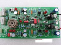
Can you snap a well lit, high definition picture of your board? The one you posted is too dark to see the color rings. If you can, I don't mind investing some time to look things over.
To make things easier for yourself in the future, when you need to short a part, there's no need to remove it. Just solder a piece of wire across the pads below the board. Less chance of lifting traces that way.
Sorry fellas just got back. Will have a play after lunch Valery.
I will also try some different LED's in the VAS rail once Valery's tests above have been completed.
Thimios - the 4th band is gold my friend.
yellow, violet, black, gold, brown
I will also try some different LED's in the VAS rail once Valery's tests above have been completed.
Thimios - the 4th band is gold my friend.
yellow, violet, black, gold, brown
Well, good and bad.
R29 was replaced with 120R. R38 was paralleled with 2 x 500R in series.
The two 500R across R38 (under the board) fried after about 10 seconds. They melted a hole right through a non conductive sheet and into the wood below. They were shunting serious current. I did not have time to take measurements. Damaged the lovely PCB's a bit dammit.
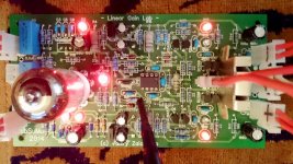
Good news - all LED's lit up immediately including the neg VAS. So we're on to something there.
I do not have anything in high watt rating around 100K, or 50K if I were to replace R38.
Valery - would it be useful to get high rating resistors in values to play with R38. It seems it may work if the current does not sound too dangerous.
R29 was replaced with 120R. R38 was paralleled with 2 x 500R in series.
The two 500R across R38 (under the board) fried after about 10 seconds. They melted a hole right through a non conductive sheet and into the wood below. They were shunting serious current. I did not have time to take measurements. Damaged the lovely PCB's a bit dammit.
Good news - all LED's lit up immediately including the neg VAS. So we're on to something there.
I do not have anything in high watt rating around 100K, or 50K if I were to replace R38.
Valery - would it be useful to get high rating resistors in values to play with R38. It seems it may work if the current does not sound too dangerous.
Attachments
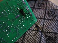
Now it's becoming a contact sport! Most of that smoke will wash off.Well, good and bad.
R29 was replaced with 120R. R38 was paralleled with 2 x 500R in series.
The two 500R across R38 (under the board) fried after about 10 seconds. They melted a hole right through a non conductive sheet and into the wood below. They were shunting serious current. I did not have time to take measurements. Damaged the lovely PCB's a bit dammit.
Good news - all LED's lit up immediately including the neg VAS. So we're on to something there.
I do not have anything in high watt rating around 100K, or 50K if I were to replace R38.
Valery - would it be useful to get high rating resistors in values to play with R38. It seems it may work if the current does not sound too dangerous.
Connecting two 500R resistors in series will give you 1k. R38 should have an extra 100k paralleled, making it 50k.
I see your not using the boards I sent. You still have some back up boards if the one your working on is damaged. I don't see any difference except for a few silk screened part values.
I have built this input twice and both worked without any changes from the schematic. The set I am running has 1/2 or 1/4 watt resistors in the r38 position.
I have built this input twice and both worked without any changes from the schematic. The set I am running has 1/2 or 1/4 watt resistors in the r38 position.
Attachments
I had one of these inputs that I fought with for a couple weeks, before throwing it behind the tire of a Komatsu loader as it backed up. Three other boards worked great.
Well, good and bad.
R29 was replaced with 120R. R38 was paralleled with 2 x 500R in series.
The two 500R across R38 (under the board) fried after about 10 seconds. They melted a hole right through a non conductive sheet and into the wood below. They were shunting serious current. I did not have time to take measurements. Damaged the lovely PCB's a bit dammit.
Good news - all LED's lit up immediately including the neg VAS. So we're on to something there.
I do not have anything in high watt rating around 100K, or 50K if I were to replace R38.
Valery - would it be useful to get high rating resistors in values to play with R38. It seems it may work if the current does not sound too dangerous.
2 x 500R in series, paralleled with 100K for R38 was definitely a bad idea. 1K in parallel with 100K. Way too much current. Please be careful - I give you precise values for troubleshooting 😉
Last edited:
Basic measurements
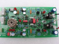
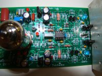
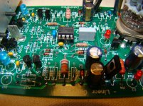
OK, here are my measurements along with some pictures.
Don't pay attention to the silk screen - this is an early prototype board.
All the values are exactly as shown on the schematic (V1.3).
Red LEDs are 3mm in diameter.
Rich, first thing you need to check again - voltage over R29.
Then - R25, R26, R32, R33. Unless you get 0.85V here - makes no sense going further.
Cheers,
Valery
Attachments


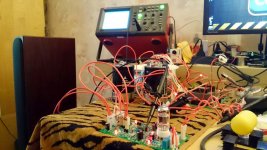
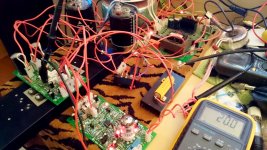
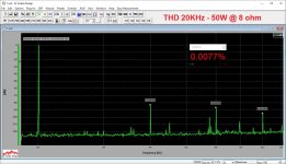
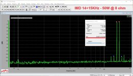
Full amp with 8 ohm dummy load
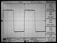
The amp with OPS and 8 ohm load.
Working perfectly. Bias is set to 100mA per output pair - you can see 20mV on DMM, measured over 2 x 0R1 resistors.
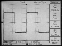
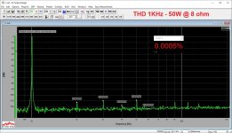
Just re-measured the spectrums for fun 😉
The amp with OPS and 8 ohm load.
Working perfectly. Bias is set to 100mA per output pair - you can see 20mV on DMM, measured over 2 x 0R1 resistors.
Just re-measured the spectrums for fun 😉
Attachments
OK back at it. Wonderful morning, managed to shift a tonne of gravel over the drive for resurfacing. Now it's a typhoon outside.
Thanks for the info Valery, had to order a few resistor values from Farnell as my available selection is woeful having used the most useful ones up on the control boards.
R38 was unaffected by my blunder so will wait for 100K to arrive but can 130K across R38 be used for a quick look?
Thanks for the info Valery, had to order a few resistor values from Farnell as my available selection is woeful having used the most useful ones up on the control boards.
R38 was unaffected by my blunder so will wait for 100K to arrive but can 130K across R38 be used for a quick look?
OK back at it. Wonderful morning, managed to shift a tonne of gravel over the drive for resurfacing. Now it's a typhoon outside.
Thanks for the info Valery, had to order a few resistor values from Farnell as my available selection is woeful having used the most useful ones up on the control boards.
R38 was unaffected by my blunder so will wait for 100K to arrive but can 130K across R38 be used for a quick look?
Yes, 130K in parallel with existing 100K is fine. It will allow us seeing if slight increase of the current through the LEDs is going to positively affect the circuit's behaviour.
Just in case - please be careful, your "experiment" with 1K could potentially damage some transistors in the VAS section. Power off immediately if something looks inadequate 😉
With 130K across R38:
V across R29 = 0.33V
V across R25 = 1.84V
V across R26 = 0.03V
V across R32 = 0.03V
V across R33 = 1.85V
And no light from neg VAS rail. Not good. The transistors are fairly well matched but I may try another set of the small signal Q's.
V across R29 = 0.33V
V across R25 = 1.84V
V across R26 = 0.03V
V across R32 = 0.03V
V across R33 = 1.85V
And no light from neg VAS rail. Not good. The transistors are fairly well matched but I may try another set of the small signal Q's.
With 130K across R38:
V across R29 = 0.33V
V across R25 = 1.84V
V across R26 = 0.03V
V across R32 = 0.03V
V across R33 = 1.85V
And no light from neg VAS rail. Not good. The transistors are fairly well matched but I may try another set of the small signal Q's.
OK. Good enough, but unbalanced. Let's return the values to the initial ones:
R29 = 150R
R38 = 100K (no additional resistor in parallel)
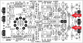
Matching is fine - something else is wrong.
Is orientation of Q10, Q13 correct? The front side with markings has to be on the right (see attached). The base lead hole is marked with a square.
Attachments
- Home
- Amplifiers
- Solid State
- Ultra-high performance, yet rather simple - hybrid and more!