yes Q10 and Q13 are correct.
Can you please measure the voltages over R41, R44.
And then - voltage at NFB terminal, referenced to ground.
What do you say if I go through the transistors group by group. It's got to be the active components at fault?
What do you say if I go through the transistors group by group. It's got to be the active components at fault?
It looks like the transistors are working fine.
Did you try to exchange the tube?
Let's also see the voltage over R9.
And the voltage at the point where R5 and R10 are connected, referenced to ground.
Voltage over R9 = 1.14V
Tried Mullard tubes as well as siemens
OK, let's do more measurements around the tube - looks like the problem is somewhere here.
First of all - just to make sure - 6.3V AC is in place and it's really 6.3V AC.
Each tube consumes 600mA, both of them together will take 1.2A. So, the transformer must be powerful enough. You can measure AC voltage on the terminal. Also, the tube's heaters are glowing with orange, as usual, right?
If that's all ok, please measure the voltages:
- across R6, R11;
- across D3, D7;
- each anode and cathode of D3 and D7, referenced to ground (the points where you see 39.3V and 37.5V respectively in post #754.
- the point where R5 and R10 are connected (collector of Q1), referenced to ground.
OK for now - let's see.
Just tried to "abuse" the circuit, powering on with the heater off (no 6.3V AC).
It's showing around -200mV DC offset (not that bad) and almost no bias (VAS current is low). As soon as the heater is on and warmed-up, the output DC trips to -47V and back to zero in about 1 second, and then settles at less than 10mV (output transistors'quiescent current starts from 50mA and reaches 100mA in about a minute or so).
It's showing around -200mV DC offset (not that bad) and almost no bias (VAS current is low). As soon as the heater is on and warmed-up, the output DC trips to -47V and back to zero in about 1 second, and then settles at less than 10mV (output transistors'quiescent current starts from 50mA and reaches 100mA in about a minute or so).
Transformer listing states: "can be configured as 2 x 6.3V 1.15A , 1 x parallel 6.3V 2.3A or 1 x 12.6V 1.15A"
Getting 6.7VAC each tube at the heater trafo terminals. Both tubes are glowing nicely. The Mullards start softer than the Siemens interestingly.
R6 = 11.8V / R11 = 12.2V
D3 = 1.69V / D7 = 1.68V
D3An = 37.5V / D3Ca = 35.8V
D7An = 37.0V / D7Ca = 35.3V
R5 and R10 are connected = -1.8V.
The above on matched but not technically balanced mullard tubes. I could do again with a balanced set.
There is a glow in the neg VAS but very faint, didn't spot it in daylight. Both VAS are quite faint.
Last edited:
BipSuMo - bipolar input LTP
Hello All,
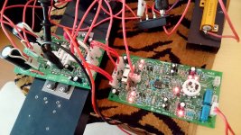
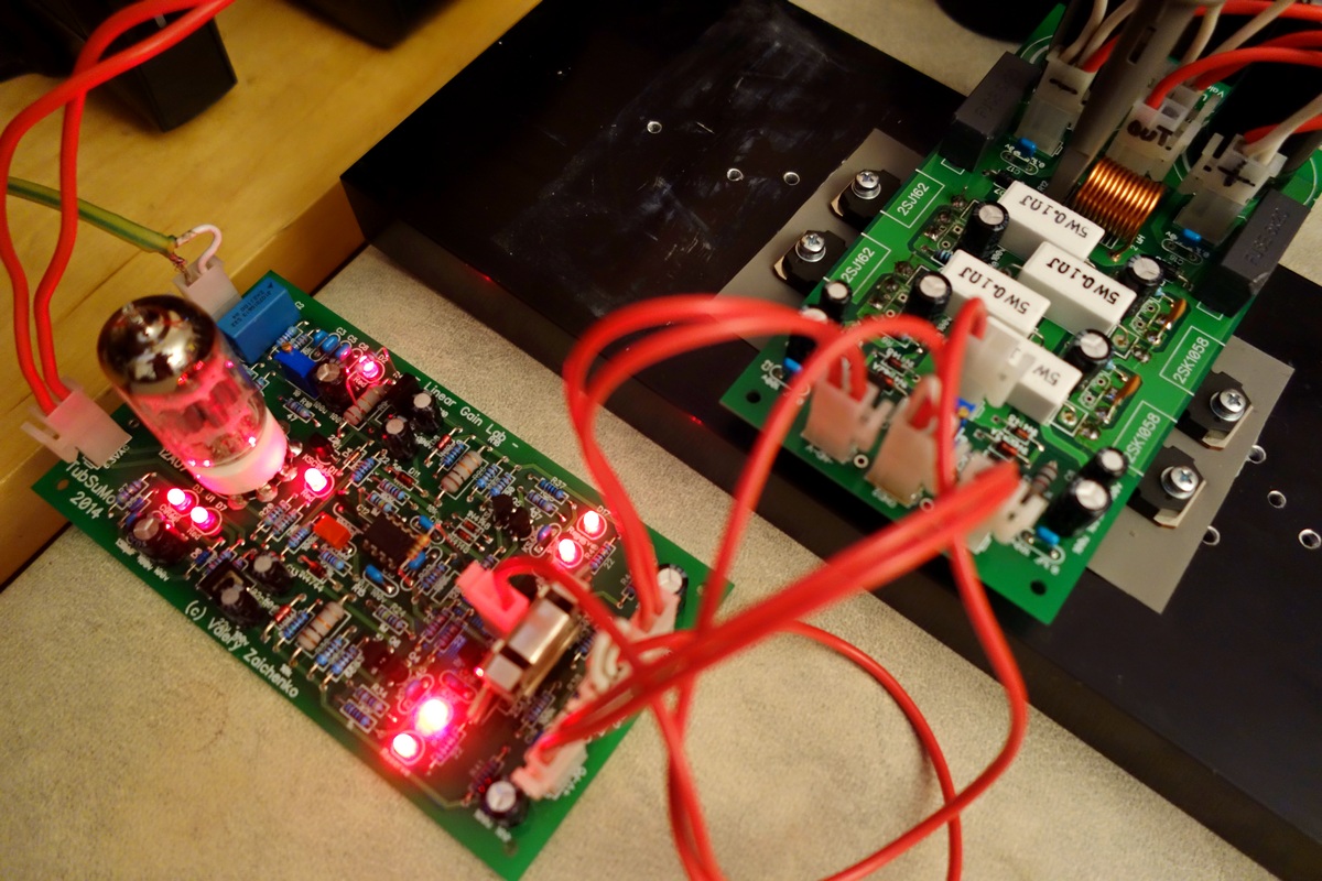
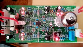
I have finally tested the option with 2 x BC550C at the input.
It requires increased degeneration for maintaining stability, all the rest is the same.
For the test, I have plugged the BJTs into the tube socket and fixed the leads with the wooden tooth sticks 🙂
Solid performance - next post will show the live spectrums with the lateral FETS and NS-OPS.
Cheers,
Valery
Hello All,
I have finally tested the option with 2 x BC550C at the input.
It requires increased degeneration for maintaining stability, all the rest is the same.
For the test, I have plugged the BJTs into the tube socket and fixed the leads with the wooden tooth sticks 🙂
Solid performance - next post will show the live spectrums with the lateral FETS and NS-OPS.
Cheers,
Valery
Attachments
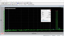
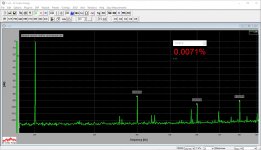
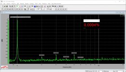
BipSuMo - THD, IMD measurements (50W @ 8 ohm)
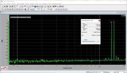
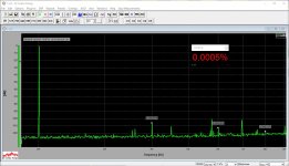
Here are the spectrums with very simple OPS - just 4 lateral FETs, and much more complex non-switching OPS.
Both perform really well, non-switching one shows lower distortion - no surprise - however the lateral MOSFETs attract with simplicity, still showing excellent performance.
Interesting observation - this is not the first time, when I see the harmonics at 20 KHz lower than the ones at 10KHz... I don't have any reliable explanation so far... non-switching specialty 🙄
All measurements are performed at 20V RMS at the output (50W @ 8 ohm load).
Attachments
-
 26 IMD 14-15KHz 20VRMS.JPG187.2 KB · Views: 158
 -
 25 THD 20KHz 20VRMS.JPG175.6 KB · Views: 158
 -
 25 THD 10KHz 20VRMS.JPG174.8 KB · Views: 176
 -
 25 THD 01KHz 20VRMS.JPG184.6 KB · Views: 172
 -
 25 00 LatFET Title.JPG61.7 KB · Views: 157
 -
 06 IMD 14-15KHz 20VRMS.JPG184.3 KB · Views: 165
 -
 05 THD 20KHz 20VRMS.JPG174.7 KB · Views: 166
 -
 05 THD 10KHz 20VRMS.JPG180.3 KB · Views: 465
 -
 05 THD 01KHz 20VRMS.JPG183.5 KB · Views: 472
 -
 05 00 LatFET Title.JPG55.9 KB · Views: 511
Hello Mr. zaichenko I am building and development of this 2014 version
* please tell me what I have to change or not to follow the board components
I follow this BOM was not or is change compared to this BOM
Thanks..🙂
Attachments
Hello Mr. zaichenko I am building and development of this 2014 version
* please tell me what I have to change or not to follow the board components
I follow this BOM was not or is change compared to this BOM
Thanks..🙂
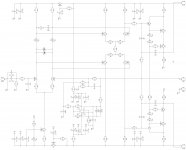
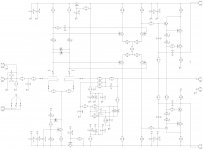
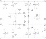
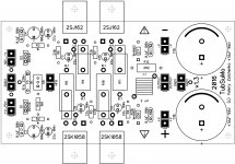
Hi, attached are the schematics and the silk screens of the latest versions. I'm running them with +/-52V rails. D8 and D9 zeners are removed.
Cheers,
Valery
Attachments

Valery
Nice work !!
I have a bit offtopic question.
Have you tryed the 6N30pi tube as a LTP front stage ?
It looks really good in sim (look at the tool bellow).
Triode / Pentode Loadline Simulator v.1.0 (20160104 www.trioda.com)
Looks like it can take as low anode voltage as ecc82 and ecc88 tubes.
I am going to get a pair of those anyway.
Regards
Peter
Valery
Nice work !!
I have a bit offtopic question.
Have you tryed the 6N30pi tube as a LTP front stage ?
It looks really good in sim (look at the tool bellow).
Triode / Pentode Loadline Simulator v.1.0 (20160104 [url]www.trioda.com)[/url]
Looks like it can take as low anode voltage as ecc82 and ecc88 tubes.
I am going to get a pair of those anyway.
Regards
Peter
Hi Peter,
I have not tried it, but thank you for the info and for the link - very useful one for hybrid builders 😉
Cheers,
Valery
thank you for sharing zaichenko gerber
but I think that there is a problem that's not good positions 22uf capacitor sizes How many children are too small while taking in my opinion should increase the capacitor 100v large size larger capacitors
he can give me my project files to edit resize foot capacitors are not
thank you very much
but I think that there is a problem that's not good positions 22uf capacitor sizes How many children are too small while taking in my opinion should increase the capacitor 100v large size larger capacitors
he can give me my project files to edit resize foot capacitors are not
thank you very much
Attachments
Valery,thank you very much for your readiness to help to all of us!
This thread is 78 pages long and schematics are undergoing changes. Can you please dump Fet final working version of schematics, for approx 40V?
Thanks a lot!
This thread is 78 pages long and schematics are undergoing changes. Can you please dump Fet final working version of schematics, for approx 40V?
Thanks a lot!
Hello Mr. zaichenko I am building and development of this 2014 version
* please tell me what I have to change or not to follow the board components
I follow this BOM was not or is change compared to this BOM
Thanks..🙂
I'm was ready to run with +/-70V rails.Hi, attached are the schematics and the silk screens of the latest versions. I'm running them with +/-52V rails. D8 and D9 zeners are removed.
Cheers,
Valery
are reasonable not, sir
I'm was ready to run with +/-70V rails.
are reasonable not, sir
Hi Duyminh,
+/-70V rails are fine, the only thing - for these rails, recommended value for R6, R11 = 22K.
Cheers,
Valery
P.S. Referring to schematic in Post #773
Last edited:
Valery,thank you very much for your readiness to help to all of us!
This thread is 78 pages long and schematics are undergoing changes. Can you please dump Fet final working version of schematics, for approx 40V?
Thanks a lot!
Hi Mlipovac, sorry - missed your post.
I will post the jFET version with +/-40V rails soon.
Cheers,
Valery
- Home
- Amplifiers
- Solid State
- Ultra-high performance, yet rather simple - hybrid and more!