Ok Jeff thanks.
I must have missed the explanation in the thread but I'm not sure what 'INP-DIR' is, certainly it isn't balanced (shame). Both inputs are decoupled the same so presume they are optional. I intended to only populate the C2 position.
Input direct (inp-dir) is direct coupled...no input capacitor. C1 and C2 are parallel they add up to the desired input cap value. My tubsumo does mid bass up so I only populated one position. For normal full range amp populate both or one with 4.7uf.
Go by his latest schematic. He made some updates to improve stability.
Yes! Sorry - just forgot to update the BOM after the latest schematic amendment. Schematic is correct.
Great recording for testing as a reference
Guys, a kind of an off-topic, but it blew be away this morning 😛
I came across it accidentally... great "material", vocal, playing, recording, mastering. This is the CD:
ODETTA - Blues Everywhere I Go - Amazon.com Music
I've got the version, released in 2003 by Top Music (TOP MUSIC 4893280080130 HK) - not sure if the one I linked is exactly the same.
Anyway - this is going to be one of my reference recordings for live testing.
This kind of amp is perfect for such an acoustic material - the sound is amazingly natural.
Cheers,
Valery
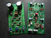
Getting there.
IPS and OPS boards are 99% stuffed. Don't you just hate it when you miss a component off a BOM list. Damn it.
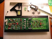
I shall go the distance on these boards and try to apply precise component tolerances where appropriate, so will do some simple matching/ selecting of the small signal transistors. As it happens the 2SA/2SC 'F' grade driver pairs I ordered showed the beta to be in the 190's for all 4 pieces.
Should the Q4/Q6 and Q5/Q7 pairs be thermally bonded to each other, or would it do any harm? The beta gain of these should be as close as possible for each pair?
Would some balance between the gain of the super pairs be useful? Usually we try and select the highest gain where possible but wondered if for instance the BC Q8/Q9 devices should be a slightly higher gain than the subsequent KS parts.
BC550/560 'C' have similar HFE rank as the KSA/KSC 'F'. It might be possible to obtain close matches between different parts.
If I'm told all this is totally unnecessary then I'll take heed, however it suits the OCD side of my nature to be precise and I enjoy the knowledge that the amp is as good as I can possibly build it. I'm sure it can't hurt 🙂
IPS and OPS boards are 99% stuffed. Don't you just hate it when you miss a component off a BOM list. Damn it.
I shall go the distance on these boards and try to apply precise component tolerances where appropriate, so will do some simple matching/ selecting of the small signal transistors. As it happens the 2SA/2SC 'F' grade driver pairs I ordered showed the beta to be in the 190's for all 4 pieces.
Should the Q4/Q6 and Q5/Q7 pairs be thermally bonded to each other, or would it do any harm? The beta gain of these should be as close as possible for each pair?
Would some balance between the gain of the super pairs be useful? Usually we try and select the highest gain where possible but wondered if for instance the BC Q8/Q9 devices should be a slightly higher gain than the subsequent KS parts.
BC550/560 'C' have similar HFE rank as the KSA/KSC 'F'. It might be possible to obtain close matches between different parts.
If I'm told all this is totally unnecessary then I'll take heed, however it suits the OCD side of my nature to be precise and I enjoy the knowledge that the amp is as good as I can possibly build it. I'm sure it can't hurt 🙂
Attachments
Getting there.
IPS and OPS boards are 99% stuffed. Don't you just hate it when you miss a component off a BOM list. Damn it.
I shall go the distance on these boards and try to apply precise component tolerances where appropriate, so will do some simple matching/ selecting of the small signal transistors. As it happens the 2SA/2SC 'F' grade driver pairs I ordered showed the beta to be in the 190's for all 4 pieces.
Should the Q4/Q6 and Q5/Q7 pairs be thermally bonded to each other, or would it do any harm? The beta gain of these should be as close as possible for each pair?
Would some balance between the gain of the super pairs be useful? Usually we try and select the highest gain where possible but wondered if for instance the BC Q8/Q9 devices should be a slightly higher gain than the subsequent KS parts.
BC550/560 'C' have similar HFE rank as the KSA/KSC 'F'. It might be possible to obtain close matches between different parts.
If I'm told all this is totally unnecessary then I'll take heed, however it suits the OCD side of my nature to be precise and I enjoy the knowledge that the amp is as good as I can possibly build it. I'm sure it can't hurt 🙂
Hi Rich,
Looks good! Clean soldering, etc. Although, I see one issue. The front-end output terminals, as well as the OPS input terminals, are suppored to be 2-pin ones. Otherwise, you connect PD+ and ND- VAS outputs to the rails. Same - with the input terminals. The 2-nd pin is the ground there!
Matched pairs are always good, although not all of them need to be matched.
Q4-Q7 - would be good to match all of them. Then, the pairs are:
Q8-Q9, Q11-Q12, Q10-Q13. Match them within each pair, but no matching between those pairs required.
Cheers,
Valery
Last edited:
Understood, thanks Valery.
Actually the Molex mini fit connectors you recommended have 4.2mm pitch spacing, the board pads have 5mm. It was difficult to get the two pin connectors in without forcing the pins apart. Can't seem to find pluggable connectors with 5mm pitch. I didn't want screw terminal blocks as the leads would be better for me orientated vertically off the board.
Actually the Molex mini fit connectors you recommended have 4.2mm pitch spacing, the board pads have 5mm. It was difficult to get the two pin connectors in without forcing the pins apart. Can't seem to find pluggable connectors with 5mm pitch. I didn't want screw terminal blocks as the leads would be better for me orientated vertically off the board.
Last edited:
These have 5mm pitch.Understood, thanks Valery.
Actually the Molex mini fit connectors you recommended have 4.2mm pitch spacing, the board pads have 5mm. It was difficult to get the two pin connectors in without forcing the pins apart. Can't seem to find pluggable connectors with 5mm pitch. I didn't want screw terminal blocks as the leads would be better for me orientated vertically off the board.
Pluggable - Terminal Blocks - Connectors & Sockets
Understood, thanks Valery.
Actually the Molex mini fit connectors you recommended have 4.2mm pitch spacing, the board pads have 5mm. It was difficult to get the two pin connectors in without forcing the pins apart. Can't seem to find pluggable connectors with 5mm pitch. I didn't want screw terminal blocks as the leads would be better for me orientated vertically off the board.
This pitch info at the sellers' pages is a little bit misleading.
See the datasheet attached. Mini fit connector can consist of a number of groups, 2 pins each. 2-pin connector is just one group.
4.2mm is a pitch between the groups. Within one group - it's 5.5mm.
The holes on my PCBs have got 5.08mm pitch for compatibility with the other types of connectors, however 5.5mm mini fit fits perfectly there - I use them in almost all of my builds.
So... order the 2-pin mini fits with no hesitation 😉
Attachments
All good with the Molex connectors now Valery. To be honest I'm still uncertain about the component dimensions in the drawing - I ordered both types of 2 pole receptacle, 2 row and single row (just to be sure) and both fit the 5.08mm pitch perfectly. The drawing would indicate that one version is 4.2mm pitch but they all fit.
To be clear, if anybody is considering 5.08mm pitch pluggable connectors - this board header fits both this single row and this dual row cable receptacle
Sorry Valery but I may have wasted your time adjusting the position of the Q10/Q13 drivers, in the end I cannot find suitable dedicated heatsinks that will fit the space or in stock. The ones I originally considered are too big and many TO-126 heatsinks seem to be too small to be adequate. So I will just have small pieces of sheet metal or ally cut. My radius is healing from a fracture so cannot snip metal very well just yet. I'll find a solution.
Still waiting for 992's /1845's from Mouser but enjoying marking out the mounting locations on the heatsink.
Attachments
Hi Rich,
Looking good! You're just confirming my experience - mini fits are compatible, regardless of what dimensions particular seller specifies on the product page
Local heatsinks for TO-126 devices can be rather light and small. Something like this would be enough:
577102B00000G Aavid Thermalloy | Mouser
Main heatsinks - perfect size.
Cheers,
Valery
Looking good!
You're just confirming my experience - mini fits are compatible, regardless of what dimensions particular seller specifies on the product page Local heatsinks for TO-126 devices can be rather light and small. Something like this would be enough:
577102B00000G Aavid Thermalloy | Mouser
Main heatsinks - perfect size.
Cheers,
Valery
The Molex connector Valery uses is called 4.2mm pitch, because that's the spacing of the mating connector. The actual spacing of the pins that solder to the board are 5mm. This connector causes a lot of confusion.
I'm so slow compared to you guys it's horrible. One does what one can eh?
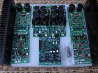
Below are all the electronics nearly ready for power. Planning the layout as the final enclosure will custom made by Schaeffer.AG, initially acrylic sheet will be used for panels. Heatsinks will be drilled and MOSFETS mounted this week when I can visit an engineering company I used to work for. They let me work in the corner quietly on a pillar drill.
The main transformer is still being made but have one spare that will give around 35V rails to get up and running.
I have this for heater supply: 15VA 2 x 6.3V Filament / Heater transformer
And this for protection supply: Transformer Toroidal 15VA 2x12V
Jeff, have sent a mail regarding the I2C connection between supply and control boards.
Attachments
Last edited:
Yep, all looks good Just in case - please power it up gradually: 1) PSU + control board; 2) IPS modules standalone; 3) The whole amplifier.
Just in case - please power it up gradually: 1) PSU + control board; 2) IPS modules standalone; 3) The whole amplifier.Thanks. Will do Valery.
One thing that came to mind is that my idea of 'tube rolling' will be cut short once the enclosure is finalised. There will no room for tube removal once the heatsinks are vertical so a good while will have to be spent trying out the 3 pairs of tubes here. I will be building Quanghau's tube I/V soon so hopefully an interesting combination can be found.
Valery - are you a DC regulated guy for filament supply or straight AC?
Thanks. Will do Valery.
One thing that came to mind is that my idea of 'tube rolling' will be cut short once the enclosure is finalised. There will no room for tube removal once the heatsinks are vertical so a good while will have to be spent trying out the 3 pairs of tubes here. I will be building Quanghau's tube I/V soon so hopefully an interesting combination can be found.
Valery - are you a DC regulated guy for filament supply or straight AC?
I am a straight AC guy 😀
But both AC lines have to be connected to the ground star at PSU via two 0.1uF capacitors.
Tested in a number of builds - dead silent setup.
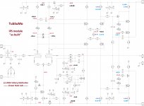
It was a lovely weekend around here so I didn't stay inside much, so sorry for the delay. Well I'm pleased to say both IPS boards seem to have what look like decent voltages around the boards.
Below is a schem with test points and voltages - supply rails are hitting the boards at just under 50V. My new measurements are in black and light blue.
The voltage drop across R32 is very low compared to the original diagram, is this ok for 50V rails?
I forgot initially to short input to ground and measured full rail voltages at input and NFB. With inputs to GND there is incredibly low DC - 0.002VDC.
Valery - at start up all LED's light apart from the two tube current LED's. Then after 8 seconds the two negative rail VAS LED's go out and the tube LED's light up.
However, with NFB shorted to ground the two negative rail VAS light back up. Is this correct? Sorry if I missed this in the thread.
I won a Velleman combi scope on ebay two weeks ago and no sign of it so I am in a dispute unfortunately. Should have got it from a real supplier. Will have one in the week hopefully.
Attachments

It was a lovely weekend around here so I didn't stay inside much, so sorry for the delay. Well I'm pleased to say both IPS boards seem to have what look like decent voltages around the boards.
Below is a schem with test points and voltages - supply rails are hitting the boards at just under 50V. My new measurements are in black and light blue.
The voltage drop across R32 is very low compared to the original diagram, is this ok for 50V rails?
I forgot initially to short input to ground and measured full rail voltages at input and NFB. With inputs to GND there is incredibly low DC - 0.002VDC.
Valery - at start up all LED's light apart from the two tube current LED's. Then after 8 seconds the two negative rail VAS LED's go out and the tube LED's light up.
However, with NFB shorted to ground the two negative rail VAS light back up. Is this correct? Sorry if I missed this in the thread.
I won a Velleman combi scope on ebay two weeks ago and no sign of it so I am in a dispute unfortunately. Should have got it from a real supplier. Will have one in the week hopefully.
Hi Rich,
I assume, you've got the values as specified in version 1.3 for 50V rails (attached), right?
With regards to power-up procedure - it would be good to switch the tube heater supply (6.3V AC) 30-40 seconds prior to switching on the main rails.
Now - testing conditions. Input is shorted (not Inp-Dir, just normal Input). NFB, PD+ and ND- are connected together - this is your output for the time being.
Let's start with measuring the voltage across D3, D7 LEDs. It should be around 1.8V DC.
Then let's change R29 to 120R. Shorten D14, D15 LEDs, leaving only one LED in each shoulder (positive and negative).
Power it on and measure the voltage over R41, R44 (100R resistors).
All LEDs should be lit up except the ones you've shorted.
Cheers,
Valery
Attachments

Ok thanks Valery - yes the component values are as V1.3.
Would you believe I have very few resistors spare below 1K - I have 100R nearest but may be able to run a few in series/parallel to get close to 120R for now.
Not to worry, Farnell deliver next day so some 120R have been ordered for tomorrow.
My LED's are 2V / 10mA types if this makes a difference:
TLHR5400 Vishay Semiconductors | Mouser
You can try 100R - it may result in a bit higher VAS current than we need, but will show us the circuit reacts properly.
- Home
- Amplifiers
- Solid State
- Ultra-high performance, yet rather simple - hybrid and more!