Here are some screen shots of the square waves.
do you mind to try lowered the cap let say to 100pF ?
I like to see what happend with high response
Thank you
It depends much more on compensation within IPS module. Those gate-drain caps only make lateral fet input capacitance equal for n-channel and p-channel (n-channel is always lower as a matter of fact).
Here are some screen shots of the square waves.
Cool 😎 Pretty similar to what I saw here as well.
CFA-fast VFA 😀

TubSumo
Hello Valery,
I've received the TubSumo PCBs from Terry (thank you Terry!) and am gathering parts to build. I've got a tube of ALF16N16W/ALF16P16W lateral power FETs that I would like to use. Would you expect a problem to use them?
I've got both +/-55 volt and +/- 72 volt ConnexElectronic switching power supplies on hand. Which would be the preferred voltage? I anticipate bog standard 8 ohm loads. I vote for 72 volts. What are your thoughts?
Any mods to these PCBs that I have missed? I am not aware of any.
Hi Carl,
Good 🙂 I didn't try Exinos Lat-Fets, although I don't see any issues with them. I will check the situation with input capacitance for them - K1058/J162 have got noticeable difference, so we have to use additional caps to balance it out.
If you go for the tube input, +/-72V DC rails are the right ones.
No PCB mods required, just if additional caps will be used at tha gates, the right position will be gate-drain - don't use gate-source places on PCB, place them directly on fet pins.
I will check the situation with Exinos fets' capacitance later today.
Cheers,
Valery
Wow! 😱
ALF16N16W/ALF16P16W ones have got input capacitance at least twice as much comparing to Hitachi/Renesas ones.
900pF / 1850pF respectively, according to the datasheet.
That means, you will have to put 910-1000pF capacitors G-D for N-channel fets.
It will probably make sense to decrease the gate stoppers' value down to 220R, sovthat the time constant stays roughly the same.
Anyway - it will be a useful experience 😉
Cheers,
Valery
Thank you Valery,
I am still collecting the parts to build. It will be a couple of weeks before I get things lit up.
I am still collecting the parts to build. It will be a couple of weeks before I get things lit up.
I must say, now that I know that the oscillation was caused by the capacitance offset in the OPS my IPS is back to the stock values. I have ordered some more boards because I want to try the FET version. I will have some extras for those interested. These are the latest version with easier to read screen print.
Valery,
I noticed that this amp doesn't seem to have the huge rail swing that the Low TIM has. It only has about a 2.5V offset at initial startup where the Low TIM has something like 32V offset.
Another thing I found is that after I got everything working I was able to get it to run fine with the JJ tubes.
Blessings, Terry
I must say, now that I know that the oscillation was caused by the capacitance offset in the OPS my IPS is back to the stock values. I have ordered some more boards because I want to try the FET version. I will have some extras for those interested. These are the latest version with easier to read screen print.
Valery,
I noticed that this amp doesn't seem to have the huge rail swing that the Low TIM has. It only has about a 2.5V offset at initial startup where the Low TIM has something like 32V offset.
Another thing I found is that after I got everything working I was able to get it to run fine with the JJ tubes.
Blessings, Terry
Hi Terry,
Thank you for the info - always good to know.
You are right, the startup swing is much lower - it was one of my initial requirements for this design - highly symmetric topology allows low offset even before NFB is fully operational.
I also like very clean measurement curves here, as you mentioned earlier, as well as excellent temperature stability 😉
Cheers,
Valery
Hi Valery,
The Low TIM hybrid is a very nice amp as well. If you ever get around to doing a new layout for that one, maybe you could fit it on a smaller board like this and with the terminal order to match.
Blessings, Terry
The Low TIM hybrid is a very nice amp as well. If you ever get around to doing a new layout for that one, maybe you could fit it on a smaller board like this and with the terminal order to match.
Blessings, Terry
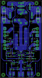
OPS . Need cleanup
A cool single-side one
Didiet, please correct the connection of C8, C9, C12, C13.
You only need C8 and C12, they have to be set between the gate and the drain - see schematic in >post #61<
Cheers,
Valery
Hi Valery,
The Low TIM hybrid is a very nice amp as well. If you ever get around to doing a new layout for that one, maybe you could fit it on a smaller board like this and with the terminal order to match.
Blessings, Terry
Agree, I especially like that one with Hex-Fet OPS.
I have actually started re-arranging its PCB - will try to finalize over the weekend 😉
Cheers,
Valery

Like this ?
Adding D7, D6, C14, C15. Moving Q1 and Q2 for heatsink if needed.
Right, exactly like this!
- Home
- Amplifiers
- Solid State
- Ultra-high performance, yet rather simple - hybrid and more!