Sorry, that should have been Q2 and Q3 from the original schematic.
The normal drop is 7.7-7.8V there.
Mostly set not by the load, but by the zeners (63V ones)...
I pulled a couple tubes out of my No GNFB boards. They are much better for DC offset but I'm still showing some voltage on the input and everything is low.
36V across R6 and R11 = .0016mA. Current is actually slightly low if I'm reading your simulation correctly. I'm between 64 and 66V on the zeners on the base of Q2 and Q3. They just seem to not be passing enough current. What current should R9 be passing?
36V across R6 and R11 = .0016mA. Current is actually slightly low if I'm reading your simulation correctly. I'm between 64 and 66V on the zeners on the base of Q2 and Q3. They just seem to not be passing enough current. What current should R9 be passing?
R9 is passing 2.38mA
Both boards were around 2.55mA until I slipped with a probe. I think I popped Q2 on one board. Is the low voltage going to cause issues? Any idea how to raise it?
Both boards were around 2.55mA until I slipped with a probe. I think I popped Q2 on one board. Is the low voltage going to cause issues? Any idea how to raise it?
How low is it? You give +/-70V to Q2, Q3 collectors. +/-61.4V are expected at the emitters. If you see significantly less - try to measure the voltages at D8, D9 zeners. If it's less than +/-62V, they've probably got not enough current through them - then the question is why.
Are you sure Q2, Q3 are soldered correctly? Both of them have to face the tube with their front sides (where the markings are). Square pad indicates the base.
Also, just to clarify - when testing with no OPS, you need to connect PD+, ND- and NFB connectors together - this is your output in this case.
I've got 73 volts at the rails. 62 volts at the emitters of Q2 and Q3. I guess they are operating fine then. All other voltage readings are low and I'm still getting some negative voltage on the input somehow. That input voltage seems to change considerably with different tubes. This is all tested with the output board connected.How low is it? You give +/-70V to Q2, Q3 collectors. +/-61.4V are expected at the emitters. If you see significantly less - try to measure the voltages at D8, D9 zeners. If it's less than +/-62V, they've probably got not enough current through them - then the question is why.
Are you sure Q2, Q3 are soldered correctly? Both of them have to face the tube with their front sides (where the markings are). Square pad indicates the base.
Also, just to clarify - when testing with no OPS, you need to connect PD+, ND- and NFB connectors together - this is your output in this case.
I've got 73 volts at the rails. 62 volts at the emitters of Q2 and Q3. I guess they are operating fine then. All other voltage readings are low and I'm still getting some negative voltage on the input somehow. That input voltage seems to change considerably with different tubes. This is all tested with the output board connected.
Very strange... Yes, 63 volts at the emitters of Q2, Q3 look ok.
But what happens with the tubes? 6.3VAC heating is in place, right?
My both channels worked right away after soldering.
I'm starting to wonder if the tubes are picking up stray magnetism on my test bench. Is this a possibility? I haven't tried to pass a signal through anything yet or even bias the output stage. I've been trying to sort out the DC offset issue first.
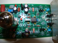
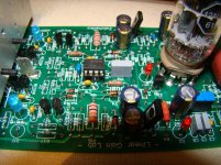
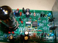
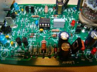
I too had a not so great first try. I hooked the frontends up to working slewmaster output stages and promptly blew the rail fuses. I have set up a bench power supply and will check voltages as per the schematic Valery added the notes to a few posts back. I'll be back when I can come up with meaningful questions. Here are a few pictures to get started.
Attachments
when checking the front end independently should there be some resistance between pd nd and nfb?
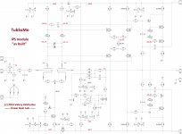
"I have marked all the important voltages here.
Red ones are referenced to Ground.
Blue ones show the voltage drop over particular resistor."
Red ones are referenced to Ground.
Blue ones show the voltage drop over particular resistor."
Attachments
Last edited:
"Connect PD+ to NFB and ND- with NFB via some lower value resistors, like 100R. VAS current is 8mA, so you should see 0.8V DC over each of the resistors or 1.6V DC over both of them (between PD+ and ND-). Your output will be at NFB connector then."
"You can install BC550 in place of the tube, also changing R5, R10 to 470R (more degeneration is required)."
"You can install BC550 in place of the tube, also changing R5, R10 to 470R (more degeneration is required)."
Last edited:
- Home
- Amplifiers
- Solid State
- Ultra-high performance, yet rather simple - hybrid and more!