It's completely unbalanced now... looks like something's wrong with soldering / transistor types / pin-outs / things like this.
I've been going over everything all afternoon. Time to take a break and then check all the resistors again.
BTW, you can also remove D4 (cathode protection, required only when the tube is in place).
If you measure the voltage drop over D2 Red LED - how much do you see?
It must be 1.72 - 1.8V as a maximum.
If you measure the voltage drop over D2 Red LED - how much do you see?
It must be 1.72 - 1.8V as a maximum.
I've switched back to a tube again. D2 started out around 1.7V, it's crept up to 1.9V now. That would likely explain the dropping voltage at D3 and D7. That's been dropping slowly all afternoon too.
Yes they are lit. I just replace D2, now it's up to 2.3 volts. This is a new batch of LEDs. Looks like I'll need to try another batch.
I mean, the LED is like a Zener - it keeps the voltage drop almost unchanged in a certain range of forward-currents. The red one keeps the V-drop somewhere at 1.75 (+/-0.3) V and it does not slip in normal conditions.
One more thought - can it be somehow, that PCB ground is not really connected to PSU ground? There are two points at OPS PCB, that have to be connected with a thick wire - GND1 and GND2. I had this wire poorly soldered in the very beginning and it drove me crazy until I realized that my IPS Groud is floating...
One more thought - can it be somehow, that PCB ground is not really connected to PSU ground? There are two points at OPS PCB, that have to be connected with a thick wire - GND1 and GND2. I had this wire poorly soldered in the very beginning and it drove me crazy until I realized that my IPS Groud is floating...
I have the input board connected directly to a power supply. No output board connected at all.
I installed two of these LEDs now (D1 and D2). Both are around 2.3 volts. They don't seem overly bright so I doubt they are being driven too hard but anything is possible.
I installed two of these LEDs now (D1 and D2). Both are around 2.3 volts. They don't seem overly bright so I doubt they are being driven too hard but anything is possible.
Mouser's search engine sucks! They call these standard LEDs but they have a 5V dropping resistor in them.
Mouser's search engine sucks! They call these standard LEDs but they have a 5V dropping resistor in them.
Aaahhh... this makes the difference 🙂
I installed a couple traffic light LEDs. They seem to be just under 1.8V now but the offset hasn't changed. I still have 9 volts across PD and ND. I'm back up to 24V at D3 and D7. Still the original issue.
I installed a couple traffic light LEDs. They seem to be just under 1.8V now but the offset hasn't changed. I still have 9 volts across PD and ND. I'm back up to 24V at D3 and D7. Still the original issue.
Something else is not right...
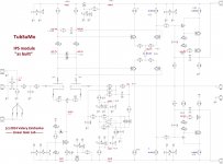
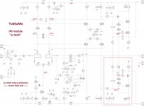
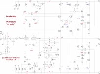
I have analyzed your voltages in more detail - it looks like the part of the circuit, showing inadequate behavior, is the bottom part of VAS (Q9, Q12, Q13).
Is Q9 = BC560?
Having zero over R33, you should also have zero over R44. But your voltage over R44 is higher than the one over R41, meaning that the bottom half of VAS pulls stronger, giving you -41.7V at the output, despite the fact that all the rest of the circuit is trying to pull it up, balancing the output to zero offset. Can you please check the bottom-right corner.
Attachments
I have analyzed your voltages in more detail - it looks like the part of the circuit, showing inadequate behavior, is the bottom part of VAS (Q9, Q12, Q13).
Is Q9 = BC560?
Having zero over R33, you should also have zero over R44. But your voltage over R44 is higher than the one over R41, meaning that the bottom half of VAS pulls stronger, giving you -41.7V at the output, despite the fact that all the rest of the circuit is trying to pull it up, balancing the output to zero offset. Can you please check the bottom-right corner.
I've rechecked every resistor on the board and gave up and replaced every transistor on the board(I hate blindly changing parts). Now I have lower DC offset and 2 volts across the output. I'll mark up another schematic in the morning and order some more LEDs out of Newark. The traffic light LEDs are meant to run at much higher current and will fail quickly at low current so I don't really trust them to do the job.
Here are my latest round of readings. I'm reading 2.2V across PD - ND. This is with the direct input shorted. If I remove the short input voltage creeps to -1.5V and DC offset climbs to -35 volts.
I will look at it. BTW, what resistor values have you got between PD+ and ND-?
I have 100 ohm resistors on them. I think these readings are off because of the LEDs. It's the voltage on the input that's got me baffled. I'm curious to see what Evanc comes up with.
- Home
- Amplifiers
- Solid State
- Ultra-high performance, yet rather simple - hybrid and more!