Hi Evan, looks good.
Yes, better test the front-ends independently before hooking-up to the OPS sections.
Jeff - thank you for re-posting the messages 😉
Yes, better test the front-ends independently before hooking-up to the OPS sections.
Jeff - thank you for re-posting the messages 😉

They look ok actually... the only thing which is strange - where does the grid voltage come from? From the grid itself?
Are you sure, R1 is 47K (not 470K by some reason)?
How high is the voltage?
Does the circuit balance itself (close to zero DC offset at the output)?
Are you sure, R1 is 47K (not 470K by some reason)?
How high is the voltage?
Does the circuit balance itself (close to zero DC offset at the output)?
I've double checked R1 several times. It's definitely 47k. Voltage is still there but lower with a 1K resistor across the direct input. Voltage changes with tubes. I think I saw -9V with one of my matched tubes. It's different with every tube and is completely gone when the tube is pulled. With a tube installed I see a small voltage start to build as soon as I turn on the heater. Depending on the tube output may balance, or may not. With -9V on the input, output is around -35V.
Last edited:
OK. If you still have +0.9V at the cathode, then your grid goes below cathode. Which is ok, if it is pulled by something negative. Otherwise, it simply cannot go below zero.
See what I mean? There's nothing within the tube, that has got some voltage below zero. So it's impossible to have the grid current in such direction, that -9V appears on the grid.
Now, the only doubt I have, is that the floating heating circuit influences the grid potential somehow (that's the only part than can potentially have any voltage relative to grid). What if you try two serial 1K resistors to the heating pins, connecting the central point (where those resistors are connected) to the ground?
Last edited:
I see exactly what you are saying. That's why I was thinking possibly an induced voltage. I even tried moving 6 feet away from the supplies thinking possibly stray magnetism. No difference at all.
I've switched to the other input now. This one seems to be stuck around -45V on the output as soon as I plug a tube in. It seemed okay with an output board attached. This is new since I jumperred it with resistors I'm going to sort that out and see how it behaves. If it's the same I'm going to convert it to BJT inputs and see what happens.
I've switched to the other input now. This one seems to be stuck around -45V on the output as soon as I plug a tube in. It seemed okay with an output board attached. This is new since I jumperred it with resistors I'm going to sort that out and see how it behaves. If it's the same I'm going to convert it to BJT inputs and see what happens.
OK. Very interesting.
Neither me nor Terry had this sort of behavior... Both of us use the floating heaters - just a separate transformer, connected to the heater pins.
Neither me nor Terry had this sort of behavior... Both of us use the floating heaters - just a separate transformer, connected to the heater pins.
I'm using a floating heater too. This input has 1 volt on R3 with the direct input shorted. I shut the heater off and can watch the voltage drop off as the tube cools. Something is up with these tubes.
I'm using a floating heater too. This input has 1 volt on R3 with the direct input shorted. I shut the heater off and can watch the voltage drop off as the tube cools. Something is up with these tubes.
In normal situation, having some 0.5-1V negative bias (grid is more negative than cathode), this tube has got a virtually zero grid current. Maybe there is some, at the order of pA... I can't imagine, what can induce -9V there...
Well, as soon as you switch off the heater, the tube stops conducting over the time, so the grid current disappears together with the voltage over R3. But where does it come in the first place? Mystery.
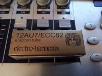
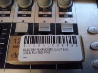
Are these the correct tubes? They say 12AU7/ECC82 on the box, 12AU7A/ECC82 EH on the tubes themself.
www.thetubestore.com - Electro-Harmonix 12AU7A / ECC82EH Audio Tubes
www.thetubestore.com - Electro-Harmonix 12AU7A / ECC82EH Audio Tubes
Are these the correct tubes? They say 12AU7/ECC82 on the box, 12AU7A/ECC82 EH on the tubes themself.
www.thetubestore.com - Electro-Harmonix 12AU7A / ECC82EH Audio Tubes
Yes, the only difference - gold-plated pins... but the tubes look exactly the same to me...
Attachments
I've just switched this input to BJT. The voltage is gone on the input but I still have a large DC offset on the output and the drivers are really conducting.
Must be around 8mA through Q10, Q13. Have you got an oscilloscope at the output?
Something still looks not correct - this thing balances itself nicely.
Something still looks not correct - this thing balances itself nicely.
I too had a not so great first try. I hooked the frontends up to working slewmaster output stages and promptly blew the rail fuses. I have set up a bench power supply and will check voltages as per the schematic Valery added the notes to a few posts back. I'll be back when I can come up with meaningful questions. Here are a few pictures to get started.
Hi Evan,
I have been worrying about whether the Tubusmo IPS will work with the Slewmaster OPS. When I first tried it, I hooked it to my JFET Slewmaster OPS and blew the fuses and a couple outputs. I repaired the OPS but didn't try it again. I wonder if the Tubsumo has too much output for the Slewmaster. I normally bring up my amps slowly with a variac and light bulb. If the bias is too high the lightbulb will alert me and I can reduce it. Unfortunately, with the Tubsumo, the IPS won't fully boot up without full rail which the lightbulb won't allow if the current is high. I just wonder if you might need to install a larger value trimmer in the Slewmaster OPS to deal with the higher output of the Tubsumo IPS. Something to think about.
Blessings, Terry
Terry,
I realized the tube ips needed full voltage to work. I hooked it up warmed up the heaters and flipped the switch.....Blown fuses. The ops seems OK...It is playing now with a different front end. I will next test the ips separately. If there is too much drive for the ops then I can compensate.
I realized the tube ips needed full voltage to work. I hooked it up warmed up the heaters and flipped the switch.....Blown fuses. The ops seems OK...It is playing now with a different front end. I will next test the ips separately. If there is too much drive for the ops then I can compensate.
Yes, I didn't mean to imply a lack of understanding. I only mentioned it because It gave me trouble when when I first tried it. You guys probably know better than me whether or not the higher output of the IPS can cause that.
Hi Didiet, in general it is possible, but not with this design. It needs more than 30V at the anodes to operate normally, so schematic will require significant redesign...
- Home
- Amplifiers
- Solid State
- Ultra-high performance, yet rather simple - hybrid and more!