The saga continues.... and with Xmas/New Year around the corner, this build is at a snails pace,
Regarding the Cathode biasing of the EL84's.
We know that in the Tubelab design the values of the cathode resistors (R112, R116, R212, R216) are 270 ohm 5W.
There are very handy calculations in http://wallofsound.ca/wp-content/uploads/2020/02/Part-5-Attachment-2.pdf
As it mentions that (I'll be using Sovtek EL84) in that build the EL84's were running at 83% of their max. dissipation, and it was a bit high, thus the value of those resistors were recommended to increase to 300 ohms.
Then in http://wallofsound.ca/wp-content/uploads/2020/02/Part-5-Attachment-3.pdf it talks of constructions using non-Hammond output transformers.
This is useful and i think this is what Stonegreen mention that is the audio was 'ill' sounding then (Post 323) "The alternative is swapping on the primary side of the OPT, orange with blue and purple with gray"
Last edited:
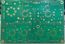
Maybe of help to some.
All connectors labelled as per Tubelab build.
B+ measuring point labelled & coloured Red.
Also the EL84 Cathode measuring points coloured Yellow when checking the bias calculations in http://wallofsound.ca/wp-content/uploads/2020/02/Part-5-Attachment-2.pdf
All connectors labelled as per Tubelab build.
B+ measuring point labelled & coloured Red.
Also the EL84 Cathode measuring points coloured Yellow when checking the bias calculations in http://wallofsound.ca/wp-content/uploads/2020/02/Part-5-Attachment-2.pdf
Attachments

Last edited:
Where does it state on the Datasheet of the EL84 the dissipation?
If 83% is classed as a bit high, then what is the safe recommended % ??
If 83% is classed as a bit high, then what is the safe recommended % ??
See the "Limiting Values" section. You got Sovtek EL84s:
14W max plate dissipation
2.2W max g2 dissipation.
Nothing will happened to the EL84, when you plug it on you can measure the real dissipation, then decide whether you need to change the bias. Even the same tube type have deviations, your EL84s may have slightly different quiescent current compared to others.
Attachments

Calpe,
Don't get too wigged-out about the 300 volt spec on the plate and screen grid. Most current production tubes will shrug off 325 to 330 all day every day. Some of the old "classic" amps that run 350+ volts can be dangerous to recent production EL84s. I worked on some old Fishers that ran 380 volts on the plates. I cut these back to around the 325 volt range.
S.
Thanks JCAlvarez and for the spec sheet. I'm still taking precautions, costs were quite high, better safe than sorrySee the "Limiting Values" section. You got Sovtek EL84s:
14W max plate dissipation
2.2W max g2 dissipation.
Nothing will happened to the EL84, when you plug it on you can measure the real dissipation, then decide whether you need to change the bias. Even the same tube type have deviations, your EL84s may have slightly different quiescent current compared to others.
Hey, no argument here, tubes are not cheap these days. EL84s are quite popular, therefore expensive, and you are right when you want to double check everything. As you said, better safe than sorry 🙂Thanks JCAlvarez and for the spec sheet. I'm still taking precautions, costs were quite high, better safe than sorry
Again thanks Steve for your support and valuable replies. I've actually fitted 300 ohm's. I think i'll be using the in-series light bulb when i get around to the First Power Up.Calpe,
Don't get too wigged-out about the 300 volt spec on the plate and screen grid. Most current production tubes will shrug off 325 to 330 all day every day. Some of the old "classic" amps that run 350+ volts can be dangerous to recent production EL84s. I worked on some old Fishers that ran 380 volts on the plates. I cut these back to around the 325 volt range.
S.
Last edited:
Just a thought.
e.g. In the WoS build the B+ was 320v and the dissipation was 13.47
So from the Sovtek EL84 datasheet jcalvarez posted the max. dissipation is 14.... that's close!
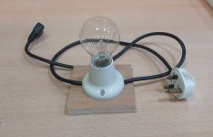
Sorting out my in-line 100w bulb instead of a variac...
First checks will of course be to establish what the B+ will measure and then with my 300 ohms
e.g. In the WoS build the B+ was 320v and the dissipation was 13.47
So from the Sovtek EL84 datasheet jcalvarez posted the max. dissipation is 14.... that's close!
Sorting out my in-line 100w bulb instead of a variac...
First checks will of course be to establish what the B+ will measure and then with my 300 ohms
Last edited:
When you say "...and then with my 300 ohms", what do you mean? Are you trying first with 270?
Issues with being close to the max dissipation are really related to long term use. Tubes even survive being driven way out of anode power specs, the first clue the anode glowing red. You are way far from that, you will have plenty of time.
PS: The PDF you are looking into is including the screen grid current in the calculation, and taking into account that the screen grid is more or less at the same voltage as the anode in an UL setup, then 13.47 is the total dissipation, which for the Sovtek is 16.2W (14+2.2)
Last edited:
The cathode resistors (R112, R116, R212, R216) were 270 ohm 5W, i've since fitted 300 ohm as a precautionWhen you say "...and then with my 300 ohms", what do you mean? Are you trying first with 270?
Issues with being close to the max dissipation are really related to long term use. Tubes even survive being driven way out of anode power specs, the first clue the anode glowing red. You are way far from that, you will have plenty of time.
PS: The PDF you are looking into is including the screen grid current in the calculation, and taking into account that the screen grid is more or less at the same voltage as the anode in an UL setup, then 13.47 is the total dissipation, which for the Sovtek is 16.2W (14+2.2)
A good description for powering up.
Unfortunately the following link does not work (Page not found):
https://wallofsound.ca/audioreviews/amplification/output-tube-biasing-anintroduction-part-2/
The following link is probably meant:
https://wallofsound.ca/audioreviews/amplification/output-tube-biasing-an-introduction/
Unfortunately the following link does not work (Page not found):
https://wallofsound.ca/audioreviews/amplification/output-tube-biasing-anintroduction-part-2/
The following link is probably meant:
https://wallofsound.ca/audioreviews/amplification/output-tube-biasing-an-introduction/
Yes, the original write up was by Steve MorleyA good description for powering up.
Unfortunately the following link does not work (Page not found):
https://wallofsound.ca/audioreviews/amplification/output-tube-biasing-anintroduction-part-2/
The following link is probably meant:
https://wallofsound.ca/audioreviews/amplification/output-tube-biasing-an-introduction/
Query.
I should be able to power up but without any valves inserted?
Especially to be able to check heater voltages.
The B+ although it wouldn't have a load i would be able to check the voltage.
I should be able to power up but without any valves inserted?
Especially to be able to check heater voltages.
The B+ although it wouldn't have a load i would be able to check the voltage.
Before that I always check for short circuits, both heater and B+ circuits. After that I always do a power up without tubes (electrolytic caps must handle the full peak B+), and measure heater voltage on tube pins, B+ rail, plates etc. At no load everything should be close to B+ peak.
- Home
- Amplifiers
- Tubes / Valves
- Tubelab SPP first timer build