The point being? The pictures Stone made you are all you need to know. Don't get lost in the weeds too much.
Where the WOS instructions won't apply is the OP transformer wiring. The Hammonds used there were of the multiple secondary type. Your single secondary trannies (with taps) will be easier to wire.
Where the WOS instructions won't apply is the OP transformer wiring. The Hammonds used there were of the multiple secondary type. Your single secondary trannies (with taps) will be easier to wire.

All i'm trying to do is get my head around all this being very cautious with these expensive transformers.
I give my greatest appreciation to you all, especially yourself Steve and Stonegreen, for the time you have taken with your help.
Weeds? More like fighting through the smog (that hit London in the 50's) 😆😆
The Hammond 1650FA https://www.mouser.co.uk/ProductDetail/Hammond-Manufacturing/1650FA?qs=gF4h2Znc3LAn53X3cMDbkQ== is very similar to my Primary Windings Transformer https://primarywindings.com/product/25w-7600-ohms-ultra-linear-push-pull-output-transformer/
All in all Stonegreen is 100% correct, thank you Stonegreen.
Though he did mention that Orange (Anode 1) & Purple (Grid 1) may have to be swopped with the Blue (Anode 1) and Grey (Grid).
Stonegreen said "You have to check for yourself whether the polarity is correct by listening.
If a squeal squawk or any untoward noise is heard from the speakers you have to swap the wires."
Thanks again Stonegreen.There are two ways to wire the OPT.
To determine the correct possibility, you must use your ears.
The alternative is swapping on the primary side of the OPT, orange with blue and purple with gray.
View attachment 1117734
I can see then that only one output impedance can be used, so it's not a matter of having a selection of 4, 8 and 16 ohms available.
No, you can use any impedance for the speakers.I can see then that only one output impedance can be used, so it's not a matter of having a selection of 4, 8 and 16 ohms available.
The 8 ohm connection is only used additionally for feedback.
Fantastic, thanksNo, you can use any impedance for the speakers.
The 8 ohm connection is only used additionally for feedback.
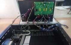
Looks like it will be a tad tricky with the line in connectors? Could you wire it so that the top plate can be pivoted on its right edge? The wiring going to the left side of the chassis can be a bit longer and routed along the back plate.
Not so much of a problem at the moment as perhaps the images show the unit in the open position.Looks like it will be a tad tricky with the line in connectors? Could you wire it so that the top plate can be pivoted on its right edge? The wiring going to the left side of the chassis can be a bit longer and routed along the back plate.
I still need to do basic checks then apply via the variac the mains supply whilst in the open position.
I'll connect a couple of in-line RCA connectors.
I'm going to read George Anderson's Tubelab build again, and of course the WofS section that refers to 1st connection to the mains etc.
Nice work. Very nice.
And I, for one, do appreciate you for asking questions when you're unsure.
And I, for one, do appreciate you for asking questions when you're unsure.
Thank you Tonyp063.Nice work. Very nice.
And I, for one, do appreciate you for asking questions when you're unsure.
I just wish I could have dedicated more time on the build.
It's taken far too long & my Transfomers stuck in the Spanish Postal for a month didn't help, causing me lots of distress.
But hey thanks to you all for your responses & help, it's truly appreciated.
Next task will be powering up the Tubelab amp and seeing those filaments glow!
You can also start with 250 volts (purple/brown) and then check the heating voltage first.
Look here:
https://www.diyaudio.com/community/threads/tubelab-spp-first-timer-build.388172/post-7187104
Look here:
https://www.diyaudio.com/community/threads/tubelab-spp-first-timer-build.388172/post-7187104
With the tolerances of the 240v, i'm going to be careful when applying power, which i hope to do this week.
So i'll check if it might be better to wire in the 250v winding instead.
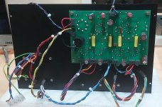
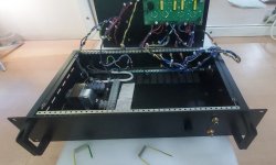
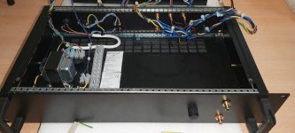
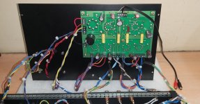
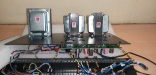
Here are a couple of images of my build as per today.
So i'll check if it might be better to wire in the 250v winding instead.
Here are a couple of images of my build as per today.
Attachments

I hope it works the first time, it's clean what you did.With the tolerances of the 240v, i'm going to be careful when applying power, which i hope to do this week.
So i'll check if it might be better to wire in the 250v winding instead.
Here are a couple of images of my build as per today.
I respect a rule, I don't attach or put away anything before having done the first tests, so if I made a mistake somewhere or if I have to track a breakdown, I can do it without undoing all the good work. .
I think this is quite important and i did it this way.
http://tubelab.com/designs/tubelab-spp/manual/
"There have been several requests for a drill template to mark the chassis. Here is a PDF of the PC board silkscreen layer. It can be printed and used as a drill template. Make sure that your printer output is 1 to 1 before drilling (lay the board on the paper and compare)."
http://www.tubelab.com/images/AssemblyManualSimpleP-P/Simple_P-P_board.pdf
Last edited:
Although this is a mono channel build (monoblock) I think for peace of mind i'm going to view again those Skunkie Designs videos on her Tubelab build.
. Her explanations are so good.
Sadly, in the Tubelab SSP http://tubelab.com/designs/tubelab-spp/ there is nothing about the tests that ought to be done when powering up for the first time. Maybe George Anderson from Tubelab could add some text about this.
So i'll also read the
http://wallofsound.wpenginepowered.com/wp-content/uploads/2020/02/Part-5-Attachment-2.pdf
that explains things very well - 'Part 5, Attachment 2. First Power-Up'
- Home
- Amplifiers
- Tubes / Valves
- Tubelab SPP first timer build