Code:
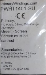
Power Transformer
Primary
220V - Blue / Orange
230V - Purple / Orange
240V - Blue / Brown
250V - Purple / Brown
Secondary -> SPP-Board
600V
Red -> T1_RED-1
Red -> T1_RED-3
Black -> T1-RED-YEL-1
6.3V
Blue -> T1-GRN-1
Blue -> T1-GRN-2
White -> NC
5V
Yellow -> T1-YEL-1
Grey -> T1-YEL-2
Purple -> NC
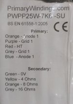
Output Transformer
Primary
Orange -> L-PRI_1-2 / R-PRI_1-2
Purple -> L-PRI_1-3 / R-PRI_1-3
Red -> L-PRI_1-1 / R-PRI_1-1
Grey -> L-PRI_2-2 / R-PRI_2-2
Blue -> L-PRI_2-1 / R-PRI_2-1
Orange/Purple may have to be swapped with Grey/Blue.
Last edited:

The labeling of the connections:

Here is the description for swapping the lines in the OPT.
(orange with blue and purple with grey):
http://wallofsound.wpenginepowered.com/wp-content/uploads/2020/02/Part-5-Attachment-3.pdf
Here is the description for swapping the lines in the OPT.
(orange with blue and purple with grey):
http://wallofsound.wpenginepowered.com/wp-content/uploads/2020/02/Part-5-Attachment-3.pdf
The secondary lines of the OPTs are connected to the speaker terminals (left/right) respectively.
In addition, the zero line (green) with L_FB-2 / R_FB-1 and
one of the other lines (yellow, orange or grey) should be connected to L_FB-1 / R_FB-2.
The experienced experts should answer which of these three lines is used. 😎
In addition, the zero line (green) with L_FB-2 / R_FB-1 and
one of the other lines (yellow, orange or grey) should be connected to L_FB-1 / R_FB-2.
The experienced experts should answer which of these three lines is used. 😎
Thanks a lot for this stonegreen. If i may i'll cross reference all the connections you've kindly given.All statements without guarantee!Code:Power Transformer Primary 220V - Blue / Orange 230V - Purple / Orange 240V - Blue / Brown 250V - Purple / Brown Secondary -> SPP-Board 600V Red -> T1_RED-1 Red -> T1_RED-3 Black -> T1-RED-YEL-1 6.3V Blue -> T1-GRN-1 Blue -> T1-GRN-2 White -> NC 5V Yellow -> T1-YEL-1 Grey -> T1-YEL-2 Purple -> NC Output Transformer Primary Orange -> L-PRI_1-2 / R-PRI_1-2 Purple -> L-PRI_1-3 / R-PRI_1-3 Red -> L-PRI_1-1 / R-PRI_1-1 Grey -> L-PRI_2-2 / R-PRI_2-2 Blue -> L-PRI_2-1 / R-PRI_2-1 Orange/Purple may have to be swapped with Grey/Blue.
Strange though that for example: -
6.3V
Blue - T1-GRN-1
Blue - T1-GRN-2
GRN would be Green? But then that would be for the wiring colours Tubelabs had on the transformer he used?
The Output Transformers, i'm going to have to be really careful with the wiring, after all the hassle i got from the postal service (not U.K.).
Anode-Grid-Cathode-Heater, i seriously need to recall those names and positions inside a Valve!
I hope to be able to spend a couple of hours a bit later today checking all this.
Thanks yet again stonegreen.The labeling of the connections:
View attachment 1115420
Here is the description for swapping the lines in the OPT.
(orange with blue and purple with grey):
http://wallofsound.wpenginepowered.com/wp-content/uploads/2020/02/Part-5-Attachment-3.pdf
I'll print that PDF a bit later and have a good read, i need to be careful on this!
Calpe,
If you number the terminal connections on the board as shown in the WOS instructions (see link) it is much easier to connect the OPTs correctly.
http://wallofsound.wpenginepowered.com/wp-content/uploads/2020/02/Part-4-Attachment-2.pdf
Make yourself an equivalency table for the wire colour differences between the Hammond in the WOS instructions and your transformers.
Here is a colored representation of my assignment from Post #302
All statements without guarantee!


All statements without guarantee!
Absolutly brillant stonegreen, many thanks for these very valuable images with detailed informationHere is a colored representation of my assignment from Post #302
All statements without guarantee!
View attachment 1115963
View attachment 1115964
View attachment 1115965
View attachment 1115966
Thanks also to Steve, always willing to help...Calpe,
If you number the terminal connections on the board as shown in the WOS instructions (see link) it is much easier to connect the OPTs correctly.
http://wallofsound.wpenginepowered.com/wp-content/uploads/2020/02/Part-4-Attachment-2.pdf
Make yourself an equivalency table for the wire colour differences between the Hammond in the WOS instructions and your transformers.
Calpe,
what is the function of the marked cable (blue arrow)?
It appears to be soldered at the position of R1, which can be replaced with the choke.
Screw connections are available for the choke (L1-1 / L1-2).
Also remember to twist the wires from the transformer.

what is the function of the marked cable (blue arrow)?
It appears to be soldered at the position of R1, which can be replaced with the choke.
Screw connections are available for the choke (L1-1 / L1-2).
Also remember to twist the wires from the transformer.
Calpe,
what is the function of the marked cable (blue arrow)?
It appears to be soldered at the position of R1, which can be replaced with the choke.
Screw connections are available for the choke (L1-1 / L1-2).
Also remember to twist the wires from the transformer.
Stonegreen, i was to fast to post that image.
The choke is now wired direct to L1-1 / L1-2.
I will remove all cables and twist them together before connecting to the terminal blocks, as recommended.
Sadly, weekends is a very difficult period to work on the Tubelab amp, let alone trying to read all these interesting and valuable posts.
I've still got to check those valuable wiring diagrams.
Thanks
Last edited:
I'm sure George Anderson, the Tubelab designer is reading these posts. 😉Brlilliant and very helpful to future builders. With your permission, George should put that on his website.
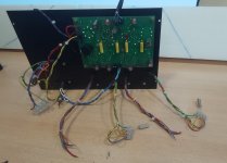
Just some images of my extremely slow build.
Just need to wire the push/pull Tx's 🤣😆🤣
I've got my fire extinguisher ready & fire blanket too🤣
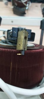
I have a AE Dimmerstat Variac, that needs a new ferrite.
The small piece of ferrite (indicated by the arrow) fits into the moving arm that determines the A.C. output.
I've actually moved it so it gives me an output, but it's not very reliable.
The manufacturer are asking a ridiculous price for a ferrite brush......
Just need to wire the push/pull Tx's 🤣😆🤣
I've got my fire extinguisher ready & fire blanket too🤣
I have a AE Dimmerstat Variac, that needs a new ferrite.
The small piece of ferrite (indicated by the arrow) fits into the moving arm that determines the A.C. output.
I've actually moved it so it gives me an output, but it's not very reliable.
The manufacturer are asking a ridiculous price for a ferrite brush......
Attachments


Last edited:
Output Transformer - Primary
Orange -> L-PRI_1-2 / R-PRI_1-2
Purple -> L-PRI_1-3 / R-PRI_1-3
Red -> L-PRI_1-1 / R-PRI_1-1
Grey -> L-PRI_2-2 / R-PRI_2-2
Blue -> L-PRI_2-1 / R-PRI_2-1
Orange/Purple may have to be swapped with Grey/Blue.[/CODE]
All statements without guarantee!
How can it be determined to what Valve the Orange/Purple and Grey/Blue cables are wired to?
Orange - Anode 1
Purple - Grid 1
Grey - Anode 1
Blue - Grid 1
Or is it a matter of using Orange/Purple to V101 and then using Grey/Blue cables to V102?
You have to check for yourself whether the polarity is correct by listening.
If a squeal squawk or any untoward noise is heard from the speakers you have to swap the wires.
Builders using non-Hammond output transformers start reading here:
http://wallofsound.wpenginepowered.com/wp-content/uploads/2020/02/Part-5-Attachment-3.pdf
I haven't gained any further experience here, Steve or others may have other tips. 😉
Be careful you don't get the orange and grey from the primary side confused the same colours on the secondary side. But that should be pretty obvious.
Stone has given you a good starting point for the OPT primary connections on the middle drawing of post 308.
You will run a twisted pair of wires form the output 0 ohm (green) and 8 ohm (orange) back to the board to make the feedback connection. The 0 ohm speaker connection should NOT be grounded to the chassis.
AS per the WOS instructions DON'T connect the lead from the 8 ohm speaker terminal to the board. This is done after the amp is up and running. I know the WOS instructions seem a bit much to wade through but if followed as you are building it should be clear and progress smoothly.
S.
- Home
- Amplifiers
- Tubes / Valves
- Tubelab SPP first timer build