Much appreciated for those web links.At 'WallOfSound' there are some good documents about the SPP.
This PDF describes the commissioning and the determination of the power dissipation, as already described by jcalvarez:
http://wallofsound.wpenginepowered.com/wp-content/uploads/2020/02/Part-5-Attachment-2.pdf
You can also find more information about setting the bias here:
https://wallofsound.ca/audioreviews/amplification/output-tube-biasing-an-introduction/
Here Steve presented a small extension to set the bias variably:
https://www.diyaudio.com/community/threads/easy-diy-tube-amp.384618/post-6983166
Have fun while reading
To be honest, i really want to avoid adjustable bias.
George Anderson, i believe in his design and build doesn't have anything like this.
All i want is a great sounding Valve amplifier, that won't be pushed hard, and runs smoothly, no mods etc.
So this is why i have emphasised about the comfortable running of the EL84 using 'correct' resistor values
Finally getting close to the wiring, just waiting for the top plate to be sprayed.
Once collected, Transformers to mount.
Then wiring will begin....
Once collected, Transformers to mount.
Then wiring will begin....
Francois, its actually a steel sheet done locally, holes drilled and sprayed black.Looks like a great job! Well done. Did you use an etching primer for aluminium?
I used the template from the Tubelab web site, carrying out the printing correctly and its exactly prints the same size as the actual PCB.
As i now have all the required holes drilled, i hope to begin mounting and wiring after the weekend.
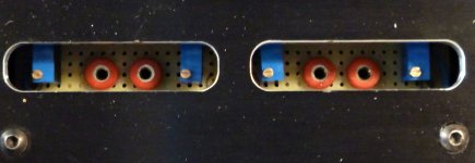
Front panel - input sockets and volume control, i will fit a small led 'on' indicator later.
Rear panel - mains input socket, mains switch, chassis fuse socket and speaker connections.
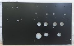
Top plate - All holes drilled for the PCB to hang under the top plate, holes for Transformers and their wires and of course holes for the Valves.
In the build i have made sure to keep the A.C. side i.e. mains transformer, choke to one side.
Audio input/output the the right side.
Very careful planning taking your time is needed, i made templates for the transformers & choke as well as the PCB holes (Valves and mounting).
Placing things to places you personally prefer (remembering AC & Audio seperation), measuring up carefully, marking holes,.
A centre punch can be used to enable the drill bit not to slip.
I actually used a 3" wood screw, these having a nice sharp point, with gentle tap it worked great, marking the holes.
Last edited:

Query to the readers, if i may about some components.
As we known the designer of Tubelabs SPP, has his web site here http://tubelab.com/designs/tubelab-spp/
Careful when reading as the site was hacked and some sections are now sadly confusing to read.
There is also very useful information on the Wall of Sound (WoS) web site.
Part 1 https://wallofsound.ca/audioreviews...ier-like-this-one-only-better-could-be-yours/
Follow their links for Part 2, 3, 4, 5 and 6.
My query is about what appears in the WoS write up.
A CL90 Inrush Limiter was used and perhaps considering the surge on switch on, makes sense to use.
But where electrically is this connected? What kind of limitation does it do?
Also a 10Ω 5W Grounding resistor was used. Why?
Where electrically is this connected?
In the WoS Part-1-Attachment-2, it shows a 1,000pF, 500v (power switch) capacitor.
This is used for what and is electrically connected where?
Also in the WoS Part-1-Attachment-2, it shows a 0.1uF, 250v (grounding) capacitor.
This is used for what and is electrically connected where?
With regards to the EL84 bias resistors, R112, R212, R116 & R216.
In the Tubelab original design they are 270 Ohm 5W.
Yet in the WoS web site, Part-1-Attachment-2, it shows different values with added comments.
It seems that in the original build by Tubelabs, it's said that the output Valves, EL84 are being pushed/stressed hard.
Thus in the WoS, they say using 300 Ohm reduces this and even depending on the type of Output Transformers, this value could be risen to 330 Ohm.
Finally a valved point saying if JJ type Valves are used then to increase the value to 360 Ohm.
I know in https://www.youtube.com/@SkunkieDesignsElectronics she says avoid the JJ Valves, which i did.
How over stressed are the EL84 being pushed using the original value of 270 Ohm?
With thanks
Electrically it is in series with the hot lead of the A/C side, after the fuse & power switch (in the WoS build)My query is about what appears in the Wall of Sound write up.
A CL90 Inrush Limiter was used and perhaps considering the surge on switch on, makes sense to use.
But where electrically is this connected? What kind of limitation does it do?
I put mine in series with the high voltage center tap
It limits the voltage at initial turn-on until it heats up. Basically it keeps the power supply caps, especially the first one, from sucking in a lot of current as they charge up from empty.
Tube rectifiers like this.
It's actually a resistor and a capacitor wired in parallel with each other & then put in the ground line.Also a 10Ω 5W Grounding resistor was used. Why?
Where electrically is this connected?
The purpose is to avoid potential hum reduction due to ground loops.
Were it me I would not bother with it at first & build the SPP as is. It's trivial to add in after the fact if needed.
With regards to the EL84 bias resistors, R112, R212, R116 & R216
In the Tubelab original design they are 270 Ohm 5W.
Yet in the Wall of Sound web site, Part-1-Attachment-2, it shows different values with added comments.
It seems that in the original build by Tubelabs, the output Valves, EL84 are being pushed/stressed hard and thus in the Wall of Sound, they say using 300 Ohm reduces this and even depending on the Output Transformers this value could be risen to 330 Ohm. Finally a valved point saying if JJ type Valves are used then to increase the value to 360 Ohm.
How over stressed are the EL84 being pushed using the original value of 270 Ohm?
The resistor value basically is what sets the cathode to anode voltage. Hence the amount of dissipation in the tube. (among other things)
However the actual value of that resistor is greatly dependent upon the actual B voltage as measured in your particular amp.
In general, a higher value resistor will be a bit easier on the output tube's dissipation along with a little less power output.
There are more factors involved, but this is a simplistic overview.
If you look at the data sheet for the EL84 (http://www.r-type.org/pdfs/el84.pdf) the published value for Rk is 270 ohms.
Contemporary tubes may not be as robust though, so going a bit higher in value may be prudent. 300-ish ohms.
Again, this value totally depends upon the voltage measured in your amp
Some questions have already been answered here:
Post #175
https://www.diyaudio.com/community/threads/tubelab-spp-first-timer-build.388172/post-7123980
Post #195
https://www.diyaudio.com/community/threads/tubelab-spp-first-timer-build.388172/post-7134033
Post #238
https://www.diyaudio.com/community/threads/tubelab-spp-first-timer-build.388172/post-7146411
This PDF describes the commissioning (270 or 300 ohm)
http://wallofsound.wpenginepowered.com/wp-content/uploads/2020/02/Part-5-Attachment-2.pdf
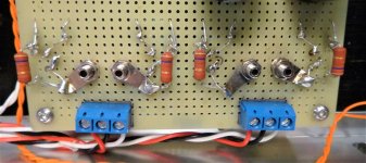
On my personal SPP I implemented an adjustable bias circuit copied from the no longer available DIYtube.com Dynaclone EL84 amp. Each tube gets its own adjustable bias trim pot. No board hacking required. Just don't install the 270, 300 or whatever ohm resistor on the board. Run wires out from the cathodes to a small perfboard with the other components. Start the amp up with the with trim pots adjusted for maximum resistance of the "stack" then tune to the EL84 dissipation desired. This also allows for perfect balance on both sides of the OPT and permits adjustment as the tubes age.
Attachments

Over here, I set up the SPP with stabilised screen supply for the EL84s, and used some 1% 3 watt 330ohm Vishay parts for the cathode resistors. Makes for easy tube matching, and some immunity to mains voltage variation. And I prefer the sound of pentode operation to UL. OPTs are 7600ohm Hammond 1650FA.
About the EL84 being pushing hard, you got Sovtek EL84, which I believe, after looking at Sovtek's datasheet, are just re-badged Soviet 6P14P, which have a maximum anode dissipation of 14W. 270 ohm will result in around 12W anode dissipation, which, for an original EL84 (12W max Pa) is borderline, but perfectly fine for the Sovtek one.
Edit: This is valid assuming B+ is up to 330V. If higher, then I would recommend starting with a 300 ohm resistor instead of 270, measure the voltage accross it and the EL84 anode voltage, calculate the power and tune the resistor if necessary to keep Pa in check.
Edit: This is valid assuming B+ is up to 330V. If higher, then I would recommend starting with a 300 ohm resistor instead of 270, measure the voltage accross it and the EL84 anode voltage, calculate the power and tune the resistor if necessary to keep Pa in check.
Last edited:
If you have not started soldering, then a tip is to use the plate to locate the tube sockets when you solder them. They can easily be offset by 1 mm in any direction, so the plate is a template to esure they are centralised.Top plate ready, drilled and sprayed
Ok, as its happens i purchased one of these and i will now connect it in series with the Live A.C. (brown) cable as you've said after the switch and i/p fuse.Query to the readers, if i may about some components.
As we known the designer of Tubelabs SPP, has his web site here http://tubelab.com/designs/tubelab-spp/
Careful when reading as the site was hacked and some sections are now sadly confusing to read.
There is also very useful information on the Wall of Sound (WoS) web site.
Part 1 https://wallofsound.ca/audioreviews...ier-like-this-one-only-better-could-be-yours/
Follow their links for Part 2, 3, 4, 5 and 6.
My query is about what appears in the WoS write up.
A CL90 Inrush Limiter was used and perhaps considering the surge on switch on, makes sense to use.
But where electrically is this connected? What kind of limitation does it do?
Also a 10Ω 5W Grounding resistor was used. Why?
Where electrically is this connected?
In the WoS Part-1-Attachment-2, it shows a 1,000pF, 500v (power switch) capacitor.
This is used for what and is electrically connected where?
Also in the WoS Part-1-Attachment-2, it shows a 0.1uF, 250v (grounding) capacitor.
This is used for what and is electrically connected where?
With regards to the EL84 bias resistors, R112, R212, R116 & R216.
In the Tubelab original design they are 270 Ohm 5W.
Yet in the WoS web site, Part-1-Attachment-2, it shows different values with added comments.
It seems that in the original build by Tubelabs, it's said that the output Valves, EL84 are being pushed/stressed hard.
Thus in the WoS, they say using 300 Ohm reduces this and even depending on the type of Output Transformers, this value could be risen to 330 Ohm.
Finally a valved point saying if JJ type Valves are used then to increase the value to 360 Ohm.
I know in https://www.youtube.com/@SkunkieDesignsElectronics she says avoid the JJ Valves, which i did.
How over stressed are the EL84 being pushed using the original value of 270 Ohm?
With thanks
The 10Ω 5W resistor and capacitor (value & type?) wired in parallel are connected where?
Maybe at this stage i'll leave out, but it would be good to know to what points they are connected to.
I will dig out a Variac i've had stored away and will need to check the B+ on my build.
I have 240V A.C. at the mains sockets, so we will see.
So i'll check if i have fitted 270Ω or 300Ω for R112, 212, 116 & 216.
Thank you tonyp063
In order to determine the dissipation, two voltages must be measured.
The voltage from B+ to ground and the voltage across resistors R112 and R116 (R212 and R216).
Now the current flowing through the resistor must be calculated:
e.g. with a measured 12V and 270 ohms this results in 0.044 amps.
The power is the voltage from B+ minus the voltage from the resistor and multiplied with the calculated current.
e.g. with a measured 320V for B+ this results in (320-12) * 0.044 = 13.6 watts
The resistor is between the earth ground from the power connector (green/yellow) and the ground on the SPP board.The 10Ω 5W resistor and capacitor (value & type?) wired in parallel are connected where?
Maybe at this stage i'll leave out, but it would be good to know to what points they are connected to.
The chassis is connected to earth ground.
Thanks stonegreen.Some questions have already been answered here:
Post #175
https://www.diyaudio.com/community/threads/tubelab-spp-first-timer-build.388172/post-7123980
Post #195
https://www.diyaudio.com/community/threads/tubelab-spp-first-timer-build.388172/post-7134033
Post #238
https://www.diyaudio.com/community/threads/tubelab-spp-first-timer-build.388172/post-7146411
This PDF describes the commissioning (270 or 300 ohm)
http://wallofsound.wpenginepowered.com/wp-content/uploads/2020/02/Part-5-Attachment-2.pdf
I've open the #Post175 in WoS.
In Post #267 (this thread) and #273 the CL90 circuit position is clear i.e. wired in series with the live (brown U.K.) cable.
But in your Post #195 you've thankfully drawn where these components go. Cheers.
The WoS link you have included is a must read (i'll have to take on board that this build is with a different A.C. supply, as we know U.K. is 240V A.C.
Thanks Steve for this.On my personal SPP I implemented an adjustable bias circuit copied from the no longer available DIYtube.com Dynaclone EL84 amp. Each tube gets its own adjustable bias trim pot. No board hacking required. Just don't install the 270, 300 or whatever ohm resistor on the board. Run wires out from the cathodes to a small perfboard with the other components. Start the amp up with the with trim pots adjusted for maximum resistance of the "stack" then tune to the EL84 dissipation desired. This also allows for perfect balance on both sides of the OPT and permits adjustment as the tubes age.
I'll take it on board and if i see its needed then out comes some Veroboard i have, trimmer pots i'll have to order
It doesn't matter where the NTC thermistor (CL-90) is installed, at L (live wire / line conductor) or N (neutral).
If your transformer has two 120 VAC primary windings, the NTC can also be placed in between.

If your transformer has two 120 VAC primary windings, the NTC can also be placed in between.
Thanks stonegreen for the information.
My Mains Tx https://primarywindings.com/product/mains-transformer-mullard-5-10-stereo/
Primaries
European primary voltages, 220V, 230V, 240V and 250V.
So i'll be using the 240V and more than likely it'll be connected as per your Post #275
Secondaries
HT winding 300V – 0 – 300V at 200mA
Heater windings 6.3V at 4A centre tapped.
Rectifier winding 6.3V at 2A tapped at 5V at 2A.
Last edited:
- Home
- Amplifiers
- Tubes / Valves
- Tubelab SPP first timer build