
Those DC voltage numbers look realistic. Unfortunately, there have been many "things" sold as "12AT7" and even more called "EL84." Few are likely to be close to the model used in the sim. The 12AT7 circuit is DC coupled so a little variance in the Mu or Gm in the first triode will cause the DC voltages on the second stage to be different. I did most of my initial testing during the development of the SPP with two sets of Sylvania 6BQ5's pulled from working amps, and about a dozen JJ EL84's. I rolled through a bunch of 12AT7's, 6201's, and a few others whose numbers I can't remember now. The component values were chosen based on an average of real measured data on all the tubes I tested. They have been fine over the years with the possible exception of the 270 ohm cathode resistors for the output tubes. These are greatly dependent on the tubes used and the actual B+ voltage.
You should have a bit over 1/3 of the voltage seen across C2 across R4 and R6 and a bit more across the tube, as seen here. Minor variations (+/- 10 to 20%) are OK, a gross difference indicates a problem. The screen and plate voltages on the EL84's is determined by the OPT and the power supply voltage. The cathode voltage is determined by the cathode resistors and the tube itself. The value of the cathode resistors R16 and R17 should be adjusted to keep the tube dissipation at a safe value. Neither the plate or the screen grid should show any redness when observed in a dark room. Some EL84's can handle 12 to 14 watts without objection (my old Sylvania 6BQ5's) but some will object to anything over 10 watts. I got two different batches of "EL84 Russian equivalent" from two different Ebay sellers many years ago and I think two or three out of about 20 tubes would work at 10 watts of dissipation.
You should have a bit over 1/3 of the voltage seen across C2 across R4 and R6 and a bit more across the tube, as seen here. Minor variations (+/- 10 to 20%) are OK, a gross difference indicates a problem. The screen and plate voltages on the EL84's is determined by the OPT and the power supply voltage. The cathode voltage is determined by the cathode resistors and the tube itself. The value of the cathode resistors R16 and R17 should be adjusted to keep the tube dissipation at a safe value. Neither the plate or the screen grid should show any redness when observed in a dark room. Some EL84's can handle 12 to 14 watts without objection (my old Sylvania 6BQ5's) but some will object to anything over 10 watts. I got two different batches of "EL84 Russian equivalent" from two different Ebay sellers many years ago and I think two or three out of about 20 tubes would work at 10 watts of dissipation.
Completely agree, there are plenty of models around for the same tube. Simulation also assumes all tubes are exactly the same, perfect match etc etc. It's just a rough guideline, but usually not too far from the average values, at least in my experience.Those DC voltage numbers look realistic. Unfortunately, there have been many "things" sold as "12AT7" and even more called "EL84." Few are likely to be close to the model used in the sim. The 12AT7 circuit is DC coupled so a little variance in the Mu or Gm in the first triode will cause the DC voltages on the second stage to be different. I did most of my initial testing during the development of the SPP with two sets of Sylvania 6BQ5's pulled from working amps, and about a dozen JJ EL84's. I rolled through a bunch of 12AT7's, 6201's, and a few others whose numbers I can't remember now. The component values were chosen based on an average of real measured data on all the tubes I tested. They have been fine over the years with the possible exception of the 270 ohm cathode resistors for the output tubes. These are greatly dependent on the tubes used and the actual B+ voltage.
You should have a bit over 1/3 of the voltage seen across C2 across R4 and R6 and a bit more across the tube, as seen here. Minor variations (+/- 10 to 20%) are OK, a gross difference indicates a problem. The screen and plate voltages on the EL84's is determined by the OPT and the power supply voltage. The cathode voltage is determined by the cathode resistors and the tube itself. The value of the cathode resistors R16 and R17 should be adjusted to keep the tube dissipation at a safe value. Neither the plate or the screen grid should show any redness when observed in a dark room. Some EL84's can handle 12 to 14 watts without objection (my old Sylvania 6BQ5's) but some will object to anything over 10 watts. I got two different batches of "EL84 Russian equivalent" from two different Ebay sellers many years ago and I think two or three out of about 20 tubes would work at 10 watts of dissipation.
Many years ago Linear Technology came into the Motorola plant where I worked to demo a piece of software called Switcher Cad. The demo guy did the usual SMPS simulations then went off the wall to show just what Switcher Cad could do on a linear circuit. The next slide on the screen showed a vacuum tube pentode configured as an oscillator and the simulation was set up to display its initial startup. Of course, we were the last two people to leave the room. Switcher Cad went through several iterations before evolving into LT spice. I have been a casual user ever since.
The research group where I spent the last 12 years of my career morphed into an IC design group, and those guys live by the simulator, so the Cadence tools they use were quite involved, accurate and expensive. I was the guy who turned their newly minted silicon trophies into a working piece of hardware which could be used, measured, and torture tested. This kept me from being chained to my computer all day long. I still look at electronics this way. I would rather build something and play with real hardware than simulate and calculate, but both methods have their place, and both are required for modern electrical engineering work.
If I have a stupid idea, I will often stick it into LT spice to see just how stupid it is. LT spice is really good at telling you that something will NOT work. It can help you find proper DC operating points, and maybe pick the component values for your first build. The actual measured performance of a circuit is dependent on the quality of the models used. Some are good, some are not, and most get iffy when the device is used in a manner that is not exactly "normal." The UNSET amp design is one example. I have built several and bounced between the sim and the test board several times before I fully understood how something that I designed actually worked.
The SPP design is very conventional and there are at least two very similar designs found in these forums. These designs simulate very well depending on the tube models.
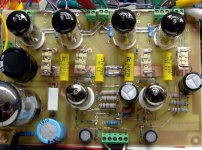
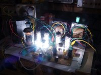
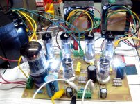
SY's RLD amp is quite similar, and I did build one with adjustable screen regulators and white LED's from the flash in a camera phone, the WLD version. Note that this is a DIY prototype PC board made before real SPP boards were available.
The research group where I spent the last 12 years of my career morphed into an IC design group, and those guys live by the simulator, so the Cadence tools they use were quite involved, accurate and expensive. I was the guy who turned their newly minted silicon trophies into a working piece of hardware which could be used, measured, and torture tested. This kept me from being chained to my computer all day long. I still look at electronics this way. I would rather build something and play with real hardware than simulate and calculate, but both methods have their place, and both are required for modern electrical engineering work.
If I have a stupid idea, I will often stick it into LT spice to see just how stupid it is. LT spice is really good at telling you that something will NOT work. It can help you find proper DC operating points, and maybe pick the component values for your first build. The actual measured performance of a circuit is dependent on the quality of the models used. Some are good, some are not, and most get iffy when the device is used in a manner that is not exactly "normal." The UNSET amp design is one example. I have built several and bounced between the sim and the test board several times before I fully understood how something that I designed actually worked.
The SPP design is very conventional and there are at least two very similar designs found in these forums. These designs simulate very well depending on the tube models.
SY's RLD amp is quite similar, and I did build one with adjustable screen regulators and white LED's from the flash in a camera phone, the WLD version. Note that this is a DIY prototype PC board made before real SPP boards were available.
Attachments
Here you are. I use the Ayumi models, there are many, many more models around.
Edit: remove .txt from the output transformer symbol file.
Edit: remove .txt from the output transformer symbol file.
Attachments
Last edited:
Thanks George for your valuable input, especially being the designer of the Tubelab Simple Push-Pull amplifier.Yes, C2 can be whatever you can fit into the board, or off board as need be. Anything below 100uF may cause hum, and I would go to at least 150 uF in a 50 Hz country. Going beyond 250 uF or so rarely offers any benefit though.
Every rectifier tube has a maximum peak current spec. This along with the total DC resistance in the transformer secondary determines the maximum capacitance. Sometimes a tube manufacturer will specify a maximum capacitance. GE calls for 3.7 amps peak, while Amperex calls for 60 uF max. 47 uF is a good limit for today's less than stellar tube quality. Exceed this and your tube may arc over internally which generally kills the tube, and possibly other parts.
The voltages depend greatly on the tubes and transformers used in the build. I have one amp that has a B+ of 430 volts and another that runs about 330 volts. Swapping in a different set of output tubes, or a different rectifier can change the voltages by 10 volts or more.
My transformers (Mains & Push/Pull) have now been shipped, so hopefully they'll arrive by this weekend.
Looking forward to the wiring and testing.
This is?@jcalvarez
Would it be possible for you to provide the LTspice files with all the include?
Many Thanks
Explanation please about this?Here you are. I use the Ayumi models, there are many, many more models around.
Edit: remove .txt from the output transformer symbol file.
I posted in #221 simulated DC values for different points. Those are quite reasonable. I was asked for the LTspice file, I shared it. Sorry if that polluted a bit the thread.Explanation please about this?
Transformers stuck in Madrid Central Post Office, needing customs clearance & payment etc.
Isn't this the effect of Brexit?
Now to to sort out via their very unfriendly Spanish Post Office web site.😡
Isn't this the effect of Brexit?
Now to to sort out via their very unfriendly Spanish Post Office web site.😡
Looks like a good idea, i might try it, thanks<LTspice> is free electronic circuit simulation software.
For example, the voltage values can be queried here.
The files offered by jcalvarez contain the circuit of the SPP.
I was missing the definition of the OTP, so I asked for the files.
jcalvarez, far from pollution! All matters with regards to the Tubelab SPP are most welcome. I'll have a look at that program, thanksI posted in #221 simulated DC values for different points. Those are quite reasonable. I was asked for the LTspice file, I shared it. Sorry if that polluted a bit the thread.
In post 226 are those 2 files for the LTspice program?Here you are. I use the Ayumi models, there are many, many more models around.
Edit: remove .txt from the output transformer symbol file.
Yes. The .asc file is the schematic, which is almost self-contained. The .asy file is the OPT symbol.In post 226 are those 2 files for the LTspice program?
I did look around for the Valves and chose Sovtek's from https://watfordvalves.com/products.asp?main=ValvesThose DC voltage numbers look realistic. Unfortunately, there have been many "things" sold as "12AT7" and even more called "EL84." Few are likely to be close to the model used in the sim. The 12AT7 circuit is DC coupled so a little variance in the Mu or Gm in the first triode will cause the DC voltages on the second stage to be different. I did most of my initial testing during the development of the SPP with two sets of Sylvania 6BQ5's pulled from working amps, and about a dozen JJ EL84's. I rolled through a bunch of 12AT7's, 6201's, and a few others whose numbers I can't remember now. The component values were chosen based on an average of real measured data on all the tubes I tested. They have been fine over the years with the possible exception of the 270 ohm cathode resistors for the output tubes. These are greatly dependent on the tubes used and the actual B+ voltage.
You should have a bit over 1/3 of the voltage seen across C2 across R4 and R6 and a bit more across the tube, as seen here. Minor variations (+/- 10 to 20%) are OK, a gross difference indicates a problem. The screen and plate voltages on the EL84's is determined by the OPT and the power supply voltage. The cathode voltage is determined by the cathode resistors and the tube itself. The value of the cathode resistors R16 and R17 should be adjusted to keep the tube dissipation at a safe value. Neither the plate or the screen grid should show any redness when observed in a dark room. Some EL84's can handle 12 to 14 watts without objection (my old Sylvania 6BQ5's) but some will object to anything over 10 watts. I got two different batches of "EL84 Russian equivalent" from two different Ebay sellers many years ago and I think two or three out of about 20 tubes would work at 10 watts of dissipation.
Skunkie Designs did mention to avoid the JJ brand, i did.
My main concern is not to drive the EL84's hard.
I recall S.Morley speaking of those 270R resistors, suggesting using 300R.
R16 - R17 would be R116 and R112 (270R 5W)?
How is that determined?The value of the cathode resistors R16 and R17 should be adjusted to keep the tube dissipation at a safe value.
Clearly the Mains Transformer and O/P Transformers puts down the requirements needed, so the B+ needs to be checked as George mentions in his post 222. What would a 'good' B+ voltage be?
The EL84 can handle 14W of total power (all values based on the EL84 Mullard datasheet), is 12W for the anode and 2W for G2. I would consider that a safe working point. In addition, the maximum anode-cathode voltage is 300V. In the schematic supplied, the tubes are set at 40mA idle current, and a Va-Vk=326V-12V=314V, therefore an idle anode power of 12.5W. Both values are slightly above datasheet values, but as Tubelab explains here (http://tubelab.com/designs/tubelab-spp/applications/) virtually every EL84 he tested worked flawlessly with those settings.I did look around for the Valves and chose Sovtek's from https://watfordvalves.com/products.asp?main=Valves
Skunkie Designs did mention to avoid the JJ brand, i did.
My main concern is not to drive the EL84's hard.
I recall S.Morley speaking of those 270R resistors, suggesting using 300R.
R16 - R17 would be R116 and R112 (270R 5W)?
How is that determined?
Clearly the Mains Transformer and O/P Transformers puts down the requirements needed, so the B+ needs to be checked as George mentions in his post 222. What would a 'good' B+ voltage be?
R116 and R112 are used to bias the output tubes, therefore they set the idle current for each tube, and thus the anode power dissipation. Depending on what EL84 you get, you may need to slightly change the value to keep the EL84 in a safe zone.
The recommended B+, quoting from Tubelab's site:
"I expect that most SPP's will be assembled this way. It is a well tested and proven combination. If this is your first amp build, this is the best place to start. The amp runs with a B+ of 320 to 340 volts using 6.6K to 8K ohm output transformers and can be run in triode, pentode or ultralinear mode. EL84's, 6BQ5's, 7189's, 7189A's and Russian substitutes can be used. I have used 6P14P's."
Regards,
Jose
PS: Just checked the Sovtek EL84 datasheet, it looks like a soviet 6P14P design:
You are very safe with 12.5W anode dissipation.
Last edited:
Thanks again to you all for your valuable input.
I'll be using Sovtek EL84, so how will i determine if R116/R112 needs to be altered in value?
What voltages should be at the Cathodes of V101/V102?
My PP Transformers (when paperwork etc is done & they get shipped out from the Madrid postal headquarters) will be 7K5.
The R16 - R17 George mentioned (Tubelab SPP designer) would be R116 and R112 (270R 5W)?R116 and R112 are used to bias the output tubes, therefore they set the idle current for each tube, and thus the anode power dissipation. Depending on what EL84 you get, you may need to slightly change the value to keep the EL84 in a safe zone.
The recommended B+, quoting from Tubelab's site:
"I expect that most SPP's will be assembled this way. It is a well tested and proven combination. If this is your first amp build, this is the best place to start. The amp runs with a B+ of 320 to 340 volts using 6.6K to 8K ohm output transformers
I'll be using Sovtek EL84, so how will i determine if R116/R112 needs to be altered in value?
What voltages should be at the Cathodes of V101/V102?
My PP Transformers (when paperwork etc is done & they get shipped out from the Madrid postal headquarters) will be 7K5.
At 'WallOfSound' there are some good documents about the SPP.
This PDF describes the commissioning and the determination of the power dissipation, as already described by jcalvarez:
http://wallofsound.wpenginepowered.com/wp-content/uploads/2020/02/Part-5-Attachment-2.pdf
You can also find more information about setting the bias here:
https://wallofsound.ca/audioreviews/amplification/output-tube-biasing-an-introduction/
Here Steve presented a small extension to set the bias variably:
https://www.diyaudio.com/community/threads/easy-diy-tube-amp.384618/post-6983166
Have fun while reading
- Home
- Amplifiers
- Tubes / Valves
- Tubelab SPP first timer build