The voltages result from the B+, and from the OTP and PT and your mains voltage.What voltages should be at the Cathodes of V101/V102?
You must determine this value through measurements in order to calculate the power dissipation.
By adjusting the resistors, you can change the current and thus the power dissipation.
R16/17 mentioned by George is from my schematic, yes, they correspond to the original R116/R112. BTW I can modify my schematic to match SPP component references, but I do not have an annotated original schematic.Thanks again to you all for your valuable input.
The R16 - R17 George mentioned (Tubelab SPP designer) would be R116 and R112 (270R 5W)?
I'll be using Sovtek EL84, so how will i determine if R116/R112 needs to be altered in value?
What voltages should be at the Cathodes of V101/V102?
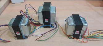
My PP Transformers (when paperwork etc is done & they get shipped out from the Madrid postal headquarters) will be 7K5.
The first thing to find out is what your B+ is going to be. You already have the desired working point for the EL84, basically something around 12W for anode dissipation, up to 1.5W for G2. The 270 ohm value is quite safe for a B+ range of 320 to 340V.
The cathode values should be around 11V to 12.5V, given 270 ohm for R116/R112, and B+ between 320V and 340V.
The first thing I do, when I'm ready to turn on a new amp with the output valves connected, is measuring the voltage in the output cathodes, making sure the cathode idle current (Ia+Ig2) is within the expected values.
Edit:
I have changed the component values to match the original schematic, can you double check?
Last edited:
Trying to get through the Spanish postal system, so they can deliver to my In-Laws! Such a very unfriendly web site and the English language is not given, only French, Portuguese or Chinese!!!!
Can you believe it! I'm fearing the worst!!!
Can you believe it! I'm fearing the worst!!!
A boring post just to mention that all the Customs clearance via the very complicated Spanish web site has now been cleared, and i expect them to be delivered in a few days, hoping by the weekend!
Calpe,
Have you posted your bill of materials yet? There is another potential builder of the SPP in the UK that might benefit from your DigiKey BOM.
Cheers, S.
Have you posted your bill of materials yet? There is another potential builder of the SPP in the UK that might benefit from your DigiKey BOM.
Cheers, S.
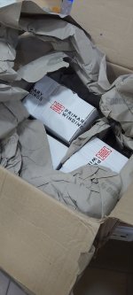
I'm fed up to the back teeth. Spanish customs have still got my Transformers in Madrid. All paperwork has been cleared weeks ago, just waiting for them to decide when they'll send down to my In-Law house.
Sorry, i haven't made a BOM list. 70% of parts i got from DigiKey, Transformers from https://primarywindings.com/ and other parts from AliExpressCalpe,
Have you posted your bill of materials yet? There is another potential builder of the SPP in the UK that might benefit from your DigiKey BOM.
Cheers, S.

Edit:
I have changed the component values to match the original schematic, can you double check?
View attachment 1099669
Jcalvarez,
I noticed the value of C100 is different than specified on the Tubelab website - 470mF instead of 1000 mF. I’m curious why such a large cap was specified in this location, and whether the 470mF makes any difference.
Calpe,
Double hallelujah with the release of your transformers (I thought someone at Spanish Customs/Post office was building an amp). Those were trying times! Looking forward to the rest of your build. Have you done the stuffing of the PCB yet?
Hi Francois,Jcalvarez,
I noticed the value of C100 is different than specified on the Tubelab website - 470mF instead of 1000 mF. I’m curious why such a large cap was specified in this location, and whether the 470mF makes any difference.
Calpe,
Double hallelujah with the release of your transformers (I thought someone at Spanish Customs/Post office was building an amp). Those were trying times! Looking forward to the rest of your build. Have you done the stuffing of the PCB yet?
My mistake, I followed an schematic that was annotated, but it was not the original. C100 changed to 1000uf.
C104 and C106 references also corrected.
Attachments
Last edited:


Work, is now under way marking where holes have to be drilled etc.Now the real work begins. Chassis work, that is.
S.
As for the wiring......and testing....
Aww, drilling, the good times!Work, is now under way marking where holes have to be drilled etc.
As for the wiring......and testing....

I hope you have some blocks under the chassis between your bench and the chassis to prevent the clamps from damaging it. Also, put a thin piece of wood or a few layers of thin cardboard between the clamp and the paper on the chassis top. Be sure to use a centre punch and a centre drill before using the drill bit.
Excellent advice. It was my first time, this photo is from a year ago. I got lucky, no damage. And also I was careful not to put too much pressure on the chassis.I hope you have some blocks under the chassis between your bench and the chassis to prevent the clamps from damaging it. Also, put a thin piece of wood or a few layers of thin cardboard between the clamp and the paper on the chassis top. Be sure to use a centre punch and a centre drill before using the drill bit.
Centre punch is indeed very useful, without it I would have had all holes over the place.
Apologies all, i've had other items i've had to attend to.
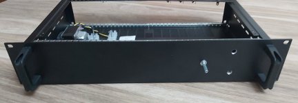
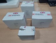
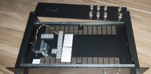
I believe i mentioned my Primary Winding Transformers arrived, after getting stuck in the Spanish postal system.
Attached are some images.
The top plate should be ready this coming week, all hole drilled.
Remaining will be the mains on/off switch, that i'll probably fit on the front facing panel, left hand side.
I need to catch up with the posts over the last couple of weeks.
Placed masking tape over the areas where i wanted sockets fitted, measured up, centre punched and drilled.
I'll add image of the top plate when i pick it up.
Just need to ensure mains earth from the input socket is connected so the case is 100% earthed.
Attachments
- Home
- Amplifiers
- Tubes / Valves
- Tubelab SPP first timer build