motzu' said:Gentlemans,
Could you be so kind to advise me how to use/replace LM 3875 with LM 3886 in Mr. Joe Rasmussen IGC tube hybrid schematic ?
This is the only chip available in this part of the world ,unfortunattely .
After reading all your excelent posts ( yeah I become a fan of this forum ) I'm still not sure what should I have to change in order to fit 3886 instead 3875
Mr.Vix wrote something about using 3886 and ECC88 or 83 which is my case too. Can I hope for a helping hand ?
Sorry for my bad english
Thank you,
Best Regards
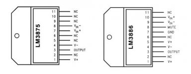
planet10 said:Once you deal with the mute the 3886 should connect pretty much the same as 3875... the ECC88 = 6922 = 6DJ8 = 6H23pi
dave
Quite right on both counts. You will need two additional components as shown in application notes:
http://www1.jaycar.com.au/images_uploaded/LM3886.PDF
This shows Mute, pin 8, a 100uF cap to ground and Rm resistor to the negative rail. If this is -35V then make RM 22K. This should draw current out of pin 8 and should be 0.5mA.
I have not yet used 3886, but I have a project comming up and the above is what I have in mind to use. You may get away with smaller than 100uF for the mute cap, but since I use 1000uF main caps I don't want the 'sag' on the negative rail to partly trigger the mute (this can cause dynamic compression) when the amp is pushed hard. The 100uF (one hundred) cap minimum should help keep pin 8 stable and prevent it.
Joe R.
PS: This thread seems to go on and on... and refuses to die.
Originally posted by Joe Rasmussen
PS: This thread seems to go on and on... and refuses to die.
🙂
and well it shouldn't
dave
Thanks for the support, Dave.
Just occurred to me, pin 8 needs 0.5mA to be drawn to de-activate mute state, so the obvious is a current source set at 1mA. This would only need to dissipate about 30-35mW, so find a small fet that handle 40V to do the job. I will be trying that and report it back here, not promising a date/time.
Joe R.
PS: Dave, while I think of it, many of the links on this thread pointing to graphics and pages etc, that are about to be lost. Is possible to run that script we discussed? I can give you the parameters again, they are simple enough.
Gentlemans,
Thank you for your answers.
As far as I understood from your kindly posts is sufficient ( and neccesarry ) to add the mute cap to pin 8 , to increase the value of RM for compatibility with 35V and that's all. !?!
Beside those, 3886 is 'pin compatible' with 3875 and the schematic of Mr. Rasmussen !?!
ECC88 will be used instead of 6922 with same voltage .
Funny - I do have ECC88 so the amp will be started ASAP
That if I'm not mistaking anything above - else I'll have some nice fireworks in my office
Thank you
I used 15 K resistor and no cap (100uF). Works fine. Tube is E88CC . You may want to use a bit higher voltage with that one, but +- 35 V will work too.
Let us know about your impressions😉
Vix
Let us know about your impressions😉
Vix
I am interested to make myself a gainclones amp (not Jlti version).
Can I use a common supply for both tube stage and the LM3875 stage?
How many Ampere we need on each supply rail?
Thanks..
Can I use a common supply for both tube stage and the LM3875 stage?
How many Ampere we need on each supply rail?
Thanks..
Originally posted by Joe Rasmussen
PS: Dave, while I think of it, many of the links on this thread pointing to graphics and pages etc, that are about to be lost. Is possible to run that script we discussed? I can give you the parameters again, they are simple enough.
I never did get an answer back from AF... i have resent to him with the parameters he gave... if he can't squeeze it into his workload, i'll just have to do it manually -- be easiest to track them down once the old ones dissapear.
dave
motzu' said:Beside those, 3886 is 'pin compatible' with 3875 and the schematic of Mr. Rasmussen !?!
No! You should do yourself a favour and read the datasheet at national.com
Attachments
Thank you leadbelly
I'm sorry but my english is not so good .By 'pin compatible' I wasn't meaning the pin order/arrangement but the aplication schematic which may use different components than 3875.
But, as far as I understood, other than the mute cap and the resistor ( some people got rid of the cap ) nothing else is changed in the schematic and I can try confident the schematic proposed by Mr. J.R.
Just today I bought a pair of LM 3886T and I'm starting the project
First in the air and then I have to project the PCB
Any hints in order to project the PCB ? Just sepcial things I need to be aware of ?
Thank you, to all of you.
BR
Originally posted by motzu'
First in the air and then I have to project the PCB
If you get the dead bug working fine, why do a PCB? The air dialectric should sound better than a PCB.
dave
Hi Moamps!
Half off topic and old question: did you try your buffer stage with the Aleph3? What do you think is it working well with it?
Greets:
Tyimo
Half off topic and old question: did you try your buffer stage with the Aleph3? What do you think is it working well with it?
Greets:
Tyimo
Tyimo said:....did you try your buffer stage with the Aleph3? What do you think is it working well with it?
Hi Tyimo,
I didn't try buffer stage with the A3. I used my diy tube preamp (3x ECC88, EAR headphone amp, with a lot of gain and low output impedance) for driving the A3. That combination was good but not spectacular.
Using a tube buffer (with Ia=ca 10mA) is a good idea if your source isn't happy with a relatively low A3 input impedance and if you don't need extra gain from the preamp to drive the A3 and your speakers.
Regards,
Milan
Hi Milan!
Thanks for the fast answer!
So, are you saying that I could try your buffer as it is with the A3?
I would like to try, if it is possible!
Greets:
Tyimo
Thanks for the fast answer!
So, are you saying that I could try your buffer as it is with the A3?
I would like to try, if it is possible!
Greets:
Tyimo
Hi Tyimo:
Yes, you could try a buffer with the A3.
Tip: If possible, raise anode voltage to about 100V and anode current to between 6-10mA.
Regards,
Milan
Yes, you could try a buffer with the A3.
Tip: If possible, raise anode voltage to about 100V and anode current to between 6-10mA.
Regards,
Milan
Can the SEWA preamp project
http://www.diyaudio.com/forums/showthread.php?s=&threadid=85952
benefit by some of experiences gained
from this JLTi topic?
I think so.
Lets share our findings.
Thanks everybody 🙂
http://www.diyaudio.com/forums/showthread.php?s=&threadid=85952
benefit by some of experiences gained
from this JLTi topic?
I think so.
Lets share our findings.
Thanks everybody 🙂
Hi everyone, little hum problem here:
http://www.diyaudio.com/forums/showthread.php?s=&threadid=101237
I saw here that the hum could be fixed by putting the tube PS ground lead closer to the speaker neg? The problem is that I have one single rectifier for the whole lot(cost and space problems), and my chassis is the actual connection between ground leads.
With my current bench setup, I get less hum by connecting the speakers negative terminals next to the potentiometer, but this is it.
There is a link to pictures in the topic I linked. So far it looks like I would need to rebuild the whole thing in an other box(or put the transformers away in an other box), right?
Guys,
about the 10kOhm resistor connected between tube pin 3/output and negative rail, will I damage anything if I connect it to ground instead?
As it is now, if I leave it connected to -40v, I get a constant 5Hz output in my speakers, and the amp goes wacko(It's almost destroying my woofers by pushing and pulling them about twice per seconds with lots of hum included) if the tube is not there warmed up.
If I leave it unconnected, well, there's almost nothing coming out of the tube's output.
If I connect it to ground, I get normal sound without wobbling or anything.
I put the gainclone in a quite small box, and I have no place for tons of rectifiers and filter caps, so I put only one rectifier. Apart from the wobble, I have the same problem as Tor Martin in this topic(Well... No one must remember, it's starting at post #201 in 2003)
Just a reminder, my post is right here:
http://www.diyaudio.com/forums/showthread.php?s=&threadid=101237
Look at the circuit... if you connect it to ground, you only present the tube with half of the potential voltage supply... which presents you with a diffirent operatoinal point needing diffirent bias...
The 40V may present you with a problem on the GC side as it wil need a huge heatsink, and will need to be kept away from speakers with low impendance dips... 8ohms+ only...
The 40V may present you with a problem on the GC side as it wil need a huge heatsink, and will need to be kept away from speakers with low impendance dips... 8ohms+ only...
Ok i read through some of the pages now (~20-30) of this topic and i got some yes/no questions.
1) Is the on Customanalogue the final one? Or is there a "better" somewhere hidden inside this thread?
2) I want to lower the output power to say somethink between 20 and 30W (as i don't need more and my speakers won't be capable of more than 40w and i want some safe region 🙂 ). Can i achieve this by the lowering supply voltage of the lm3875 (say to ~+-25V) and keep the rest of the circuit as it is without bad effects on the sound quality?
3) If i can lower the rail voltage as i did describe above, can i use the same psu as for the tube for the lm3875 on the homepage above(customanalogue) and will a 200VA trafo be sufficient then?
greets and thanks,
Patrick
- Status
- Not open for further replies.
- Home
- Amplifiers
- Chip Amps
- Tube with Power IC Output Stage - JLTi