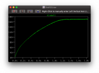
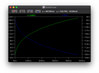
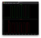
Very interesting paper on stability issues with series converters: https://etheses.whiterose.ac.uk/13951/1/PhD_Thesis_ACSE_XinZhang.pdf
I've also found an interesting 12-325V UC3843 implementation. The LT1243 is essentially the same chip, but there's a couple of implementation details - namely the fb-compensation and the slightly adjusted isense. He uses a flyback with a current sense coil, I'm using a straight boost and direct current sense resistor. He's using larger transformer and an inductor-based non-dispersive snubber (same as the one I had on originally before stripping it down to simplify).
Needless to say, the design is now operating (although a few defcons but not as bad as it was) - already up to 90V with just 47uF!
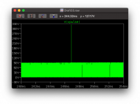
Output noise as it is at 90V:
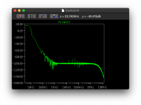
Needless to say, the design is now operating (although a few defcons but not as bad as it was) - already up to 90V with just 47uF!

Output noise as it is at 90V:

So I've found something with LTSpice.. the problems with stability seem to have been todo with grounds. I linked the grounds together rather than use the ground node and lo-and-behold I'm no longer getting DefCon! Almost like LTspice treats the global ground node different depending on where it's connected.. now with fewer ground points it's happy as Larry compared to previous runs.
What made me think if grounding was some ground bounce mosfet switch ringing. Now with that connected it's behaving.
What made me think if grounding was some ground bounce mosfet switch ringing. Now with that connected it's behaving.
I've started looking at 48V based systems so that the boost easier. I'm wondering if it's not time to have a look (finally) at bridge boosters.
https://www.st.com/resource/en/appl...t-halfbridge-converter-stmicroelectronics.pdf
If there's something similar to the LT1243 for that topology that allows step up that would be good. I'd still keep the 240-24Vdc OTS PSU. It had occurred to me about the use of a full wave (higher voltage but drop in current) rather than a halfway (more current less voltage).
The more complex transforms the more likely it's not to have an OTS transformer available at Mouser etc.
So my thinking now is:
240Vac -> OTS SMPS -> 24Vdc -> Half-bridge dual then have each transformer -> rectified parallel -> Single reserve cap rail.
This approach doesn't use a AC waveform across a single transformer but instead two transformers running in parallel but at 1/2 rate.
The output then becomes rectified with a diode (keep it simple ) and then both join into a single B+ rail for the final reserve cap & filters
As we're doing both in parallel, they're not sharing the same iron. The AC with the same transformer is to keep the voltage different minimal making it cheaper.
This technique means we're not switching more than single switching but simply slower. The resulting B+ noise/ripple is therefore still at 2x the rate for common noise from both switches and 1x rate for individual channel noise.
This topology also supports CCM based switching - I can bias the MOSFET to always provide a little current to minimise harmonics. The design would therefore always be pumping a minimum amount of energy into the transformers and thus requires the power to be utilised. This fits with the class A approach and the need for bias current.
I'll also be looking for both current limiting and voltage feedback regulation, so I have to use a half bridge capable controller with those features with external gate drive.
So all that exists is for me to find a compatible IC and model this up.
So the 'hybrid' (polite term) half bridge is a dual flyback with secondary full bridge rectification:
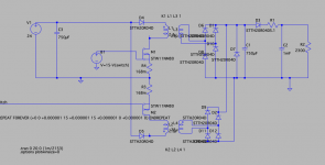
The two transformers are off the shelf (no guesses here)- my old favourite Coilcraft capacitor charging transformers. 1500V insulation and capable of 12V 50A driving to 500V. The design uses two, interleaved at 100Khz so each transformer is operating at it's Fsw 50Khz.
The output once rectified sees 100KHz pulses.
At the moment it seems very capable. Only issue is that it's not limiting current (no surprises here) but the results are good.
I'm currently reviewing the LTC3723 which can support both half and full bridge current mode operation. Then have the synchronous drive run the two mosfets with the voltage feedback from the secondary Vout and the current drive watching the combined single current sense resistor.
LTC3723 Datasheet and Product Info | Analog Devices
The fun will come with duty cycles and the changes to the noise frequency.
I'm also considering adding a small bias to the mosfet so that it is always running in CCM mode. It would be good to find a controller that allows this.
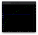
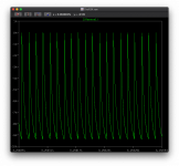
The model progressing.. up to 72V and the current draw from the 24V supply is 6A (144W).
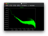
Seems to be running at 2x~70KHz, I still need todo some tuning, but I'll leave this one going and see if it copes with running to full power and to see the noise level.
Let's see what this will look like at 230V tomorrow morning
So attempt 1 lessons learned, the transformer will probably need 14A to provide 200V as a guess given the RMS for this is 7A:
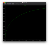
However this is another option that we can do to improve this. This attempt was to see if the current delivery and the mechanism was possible- it would have provided 2A!
As we have two transformers in parallel at the moment working alternate. There is an option to simply use the isolation to have the two transformers running in series on the secondary with capacitors creating a full wave bridge, just like AC:
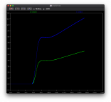
We should still have way more than enough current for our needs.


However this is another option that we can do to improve this. This attempt was to see if the current delivery and the mechanism was possible- it would have provided 2A!
As we have two transformers in parallel at the moment working alternate. There is an option to simply use the isolation to have the two transformers running in series on the secondary with capacitors creating a full wave bridge, just like AC:

We should still have way more than enough current for our needs.
Last edited:
Good old voltage doubler. I've been avoiding due originally having limited current, also they are 'spongy' in terms of regulation with quite a lag.
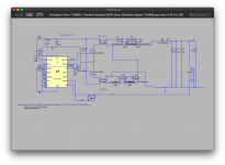
However this is running at 160V and still going up. I knew this would work but it's an awful lot of fuss to increase voltage and maintain the desired current.

However this is running at 160V and still going up. I knew this would work but it's an awful lot of fuss to increase voltage and maintain the desired current.
Interesting paper summarising.
(PDF) Survey on non-isolated high-voltage step-up dc–dc topologies based on the boost converter
(PDF) Survey on non-isolated high-voltage step-up dc–dc topologies based on the boost converter
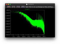
So diode noise and part of the reason for steering clear of diode based voltage doublers.. however at least the noise for the switching remains out of the audio spectrum. It should be noted that the Cout is only 3mF not the normal 6mF so the LPF would be less effective.
One of the interesting topologies in the paper I linked to previously (number 14a/b) is that it uses 3-state switching boost with alternating switches. This seems better for the switches but also for handling more power.
Current handling?
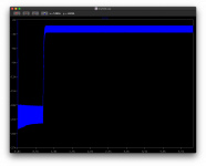
Initial Cin inrush, then 18-22A inrush for the switching to charge and bring the system up to 220V, at which point the voltage regulation starts and the current is dropped to 2-3A. Naturally that inrush needs some attention but the coilcraft capacitor charger transformer is capable of 50A at 12V or 25A at 24V at 500V output.
Average wattage on the switch indicates 81W so there's still some work to be done..
So this would work and solve my needs.
However it's not particularly efficient I suspect.
Last edited:
Why not just build a flyback out of cheaper cores and cheaper switching IC?
45Khz and a 1068 core posted earlier is much simpler, lower parts count as well.
Why do you want to charge a mF to several hundred volts? A flyback is fast enough to respond to load transients.
45Khz and a 1068 core posted earlier is much simpler, lower parts count as well.
Why do you want to charge a mF to several hundred volts? A flyback is fast enough to respond to load transients.
Why not just build a flyback out of cheaper cores and cheaper switching IC?
45Khz and a 1068 core posted earlier is much simpler, lower parts count as well.
Why do you want to charge a mF to several hundred volts? A flyback is fast enough to respond to load transients.
Mainly noise. What I was attempting to get to something low part count hence not going down the Doubler route, just IC and a transformer with space for some caps and if need be a regulator.
However you're right. I'm starting to see that the SMPS almost doesn't need large caps.
I forgot to say there's also a small issue of current (600mA was the original rough max target although 480mA being the maximum use).
I'd use a low ESR DC link for the output, 20uF 800VDC MKP or something. no need to use 1mF.
UC3843 is good enough.
UC3843 is good enough.
I'd use a low ESR DC link for the output, 20uF 800VDC MKP or something. no need to use 1mF.
UC3843 is good enough.
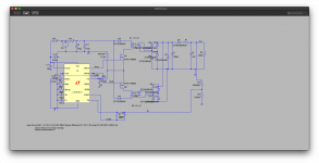
So I've taken the new learnings back to the UC3843 (well the LT143 which has a model) - using the simple boost converter:
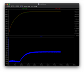
600mA+ at 220V+ on 24V (blue). Using 20uF and 80uF output caps. I've also switched to two 700uH inductors in parallel.
The main issue I found was getting the right RC time and inductance matching the limitations of current.
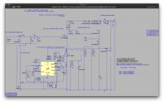
Will tidy and optimise a bit.
- Home
- Amplifiers
- Power Supplies
- Tube use? 24->300V large cap charger with 300V 150mA reg
