Tekko,Those arent heatsinks!! You need something atleast 10x larger than that.
aw..... then i'm going to have headache..... here those heatsink are rare things... and its expensive to purchase thodr, can give me rough dimension ? (width x length x height)
10 by 10 centimeters, squared aluminium blade, one to each power
transistor will be good enough.... you can bend it and make it U shape, or L shape.... well, this up to you.
Aluminium from old food pots may help... that aluminium rounded thing we use to make pizza.... that aluminium can be good ..just cut it and fold it the way you want.
regards,
Carlos
transistor will be good enough.... you can bend it and make it U shape, or L shape.... well, this up to you.
Aluminium from old food pots may help... that aluminium rounded thing we use to make pizza.... that aluminium can be good ..just cut it and fold it the way you want.
regards,
Carlos
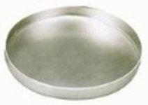
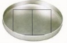
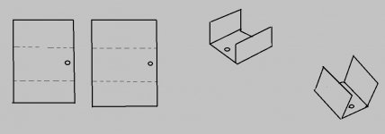
Diy heatsinks
In three steps you can make yours.
-1 find a pizza pot...old or new.
-2 trace lines and cut it the way shown.
-3 bend it as shown i image three.
ready to go!
Carlos
In three steps you can make yours.
-1 find a pizza pot...old or new.
-2 trace lines and cut it the way shown.
-3 bend it as shown i image three.
ready to go!
Carlos
Attachments
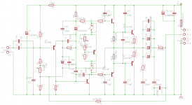
wahaha, uncle, I'm planning to reconstruction the amplifier (well.... alot of problem) so there is some question about the circuitry.
What is the usage of C16 and C17, which is 680pF ? It seems serve no purpose.
About the heatsink, i seems to find something interesting, alot of steel, but seems not thermal conductive enough (high thermal resistant)
It is the fluorescent lamp ballast casing, i have alot of them (just replace them, almost throw it away) They are long square hallow tube, after emptied them, it seems i can cut them into piece and use with stacking. like http://image.made-in-china.com/2f0j00cBvtqYRkgWbV/Fluorescent-Lamp-Bracket.jpg
But they have a layer of paint on outside, which low thermal conductivity i think.
may i know at least how to do the ground relate to the chassis and power supply ? (connection between them)
Member
Joined 2009
Paid Member
Carlos,
What is the purpose of R18, that connects the output from the speaker terminal (i.e. after the dc blocking condensor) to the bottom of the feedback shunt capacitor ? - is this to alleviate turn-on and turn-off transients whilst the output and feedback condenser are charging up ?
Why is the bottom of the feedback shunt capacitor connected to the input -?
Last edited:
It is a feedback, but i cannot remember
This changes damping, is a voltage divider considering speaker and that resistor, but i cannot remember... three year is to much time to my memory.
I knew..but i do not remember the reason why.
I hope someone remember.
Have you readed the entire thread?.... i do think i have explained that..before it was deleted from my mind.
Try to simulate it to discover the effect,... with and without it..use complex load as a speaker instead of a resistor as speaker...i have no more simulator files of this amplifier.
regards,
Carlos
Last edited:
I see, i often use frame ground... in special to home prototypes
It is alike a picture frame...the wooden surrounding of a picture, the frame.
I do think star ground is better, but not that easy to make the pcboard using star ground...using frame is easier..when you need ground then you have in waiting for you in the neighborhood..the resistance is so small that ground loops will not be a problem..my copper tracks are filled with solder... resistance is 0.001 ohm or less.
Well...there are guys that says this is enough to oscillate...i am not having the oscillation these guys said i would have.
regards,
Carlos
I also want one....
Hi, I need a small single supply amp and after searching the forums I decided on DX-Trust. Thie is my first amp project, so I'd like to make it simple.
It's now under construction, I modified the board layout to fit for my heatsink and available parts and also turned the bias servo (vbe) upside down so it now has a pnp transistor (bd140). The outputs 2sa1941 and 2sc5198 are good for a 70w amplifier according to Toshiba. As output caps I will use four times 2200uF/35V, totally 8800uF, that should be sufficient. Otherwise it will follow the original schematics.
Well, its time to start soldering the parts into place.....🙂
Attachments
Sound is very nice...i really like the old style sonics
It is very good amplifier...you gonna love it.
regards,
Carlos
It is very good amplifier...you gonna love it.
regards,
Carlos
Member
Joined 2009
Paid Member
Hi, I need a small single supply amp and after searching the forums I decided on DX-Trust. Thie is my first amp project, so I'd like to make it simple.
It's now under construction, I modified the board layout to fit for my heatsink and available parts and also turned the bias servo (vbe) upside down so it now has a pnp transistor (bd140). The outputs 2sa1941 and 2sc5198 are good for a 70w amplifier according to Toshiba. As output caps I will use four times 2200uF/35V, totally 8800uF, that should be sufficient. Otherwise it will follow the original schematics.
Well, its time to start soldering the parts into place.....🙂
Hi
can I use this amp with this transistor for 2 ohm speakers ?
thanks
I don't think so.... better not to use
It will not be damaged..but sound will not be good...was not made to be used this way.... was not designed to produce high power.
Was conceived to produce a sound "vintage style"...not to produce power...was conceived to use sensitive speakers... full range speakers.
Check the thread ( i cannot remember)... i suppose it was not suggested to be used with 2 ohms loads...maybe 4 ohms.
regards,
Carlos
Thank you very much for comments and encouragements.
My build is progressing rather slowly (as dyi projects should do) and I am still hunting for parts.
But half of the parts are already in, the transistors will be next after I have figured out how to match them without a hfe-meter. I wonder if a simple setup like this:
Successfully choose complementary bipolar transistors | EDN
or this:
Transistor matching
will do the trick?
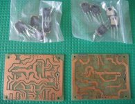
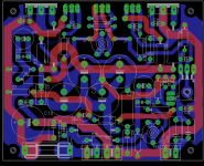
About the PCB's, they are made using the toner transfer method. I did a lot of experimentation and had a hard time finding the right paper type. So far I had the best luck with thin glossy advertising paper. Double sided PCB's are challenging since the alignment is difficult and the whole arrangement moves and changes shape during the ironing. I ruined one board and must have re-ironed the patterns at least fifteen times before getting it right!
I choose to make the PCB's double sided as an exercise and also to get better current flows to the output transistors. I made a few mistakes in the layout, mostly caused my designing the boards before having the actual parts at hand. Good to know until next time...
Next step is to design the power supply board but that should be relatively easy.
More to come, I will keep you informed as the build progresses.....🙂
My build is progressing rather slowly (as dyi projects should do) and I am still hunting for parts.
But half of the parts are already in, the transistors will be next after I have figured out how to match them without a hfe-meter. I wonder if a simple setup like this:
Successfully choose complementary bipolar transistors | EDN
or this:
Transistor matching
will do the trick?
About the PCB's, they are made using the toner transfer method. I did a lot of experimentation and had a hard time finding the right paper type. So far I had the best luck with thin glossy advertising paper. Double sided PCB's are challenging since the alignment is difficult and the whole arrangement moves and changes shape during the ironing. I ruined one board and must have re-ironed the patterns at least fifteen times before getting it right!
I choose to make the PCB's double sided as an exercise and also to get better current flows to the output transistors. I made a few mistakes in the layout, mostly caused my designing the boards before having the actual parts at hand. Good to know until next time...
Next step is to design the power supply board but that should be relatively easy.
More to come, I will keep you informed as the build progresses.....🙂
Attachments
Hi, I need a small single supply amp and after searching the forums I decided on DX-Trust. Thie is my first amp project, so I'd like to make it simple.
It's now under construction, I modified the board layout to fit for my heatsink and available parts and also turned the bias servo (vbe) upside down so it now has a pnp transistor (bd140). The outputs 2sa1941 and 2sc5198 are good for a 70w amplifier according to Toshiba. As output caps I will use four times 2200uF/35V, totally 8800uF, that should be sufficient. Otherwise it will follow the original schematics.
Well, its time to start soldering the parts into place.....🙂
Wow. That is a very nice double side diy PCB!!! You made it smaller
 it looks AWSOME! Hats off to your work 😉
- Status
- Not open for further replies.
- Home
- Amplifiers
- Solid State
- Trust, the most delicious Dx Amplifier