Okay so after more testing, more boards and more communicating with TI, it seems like the rising 2nd order HD towards low frequencies is endemic to the TPA3251D2.
My contact only had the previous balanced input EVM to confirm things with but it would appear that the TPA needs a very low output impedance power supply to perform as the datasheet would suggest.
When using 'standard' as one may call them, power supplies you see the rising 2nd order and the degree to which it rises depends on the supply. At one end of the spectrum you would have say a laptop brick on the end of long cables, at the other end of the spectrum a bench PSU with remote sense lines that regulates to a pretty much zero ohm output impedance at the point of load. The latter shows no rising 2nd order with others showing an issue.
If what I've seen is correct then using longish cables is also a big nono. For example I ran a test with my bench PSU and there is a rather large change in performance from using 10cm cables to using ~50cm cables.
Clearly the power supply is critical, as are other aspects of the design to minimising this. Having a large amount of local bulk decoupling helps a lot. I have since changed my 470u caps to 2200u caps as TI do in the final EVM. And the Cstart cap also make a difference, increasing this to 470n - 1u reduces the problem.
Would it be of interest to test yet another layout? So I would send you one of my PCBs with all the "special" parts (buck ic, inductor, ferrites) included.
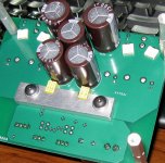
(Actual got 2x3000uF on board, capable of 2x4.5A ripple)
(Actual got 2x3000uF on board, capable of 2x4.5A ripple)
hmm, looks like a poor power supply rejection in that case.🙁
I'm not sure if its PSRR specifically. The chips PSRR should increase or remain constant at low frequencies and the loop gain will carry on going up as frequency decreases too. Why this would manifest specifically as only low frequency 2nd order distortion is puzzling to me. Especially as the distortion rises with falling frequency. Usually it's the other way around, it's the high frequencies that are affected, no only because of the reducing PSRR and loop gain, but also because high frequencies tend to couple better into places you don't want them.
The degree to which the problem manifests depends on how much power the chip is asked to put out. Yet with TIs remote sensing bench power supply you see no THD degradation whatsoever up until clipping. Even with remote sensing at the board input you're still going to get ripple occurring on the supply traces leading up to the chip.
Either way it shows there's room for improvement in the design department. Thankfully it's only 2nd order and of absolute levels that aren't going to be objectionable with a decent PSU. Still keeping wires short and the bulk decoupling low ESR and of decent capacity is highly advisable.
Would it be of interest to test yet another layout? So I would send you one of my PCBs with all the "special" parts (buck ic, inductor, ferrites) included.
(Actual got 2x3000uF on board, capable of 2x4.5A ripple)
Can do doc but all my TPA3251s are already soldered in place and are in use. I would rather not desolder any and risk destroying one. TI were kind enough to supply me with some preproduction models to try and solve the rising THD issue as they apparently weren't aware of it either.
If anyone wants a working stereo board that accepts both SE and balanced inputs though TI now have availability on the evaluation module. It's $250.
Last edited:
Agree with you,
but from a digital source, there is no DAC in the path to the TAS5548 .... it can have positive impacts on the quality vs superior THD of the TAS3251D2.
Another positive argument: the cost. If you remove good DAC and good interconnects from the path, it is less expensive.
Am I wrong?
The most "digital" is when it's open loop. But this requires a very good (expensive) regulated power supply. Eventhough the input is digital, there is an analog feedback loop, when choosing a closed loop design. Therefor essentially the amplifier is still analog. The feedback network will send an analog signal back into the input of the amplifier, eventhough the original signal was digital. The only way to keep the signal 100% digital is to avoid the feedback network = open loop architecture.
Last edited:
Interesting Chip... An improvement over the TAS5611A ?
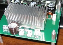
I plan on operating this chip @ 15V. I will be using 10uh Wurth PD XXL , Mundorf caps, Wima PPS, Jensen Transformers, Linear LTC3083, and the Sanken HWB 60W.
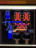
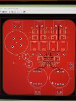
110mm x 115mm 4-layer 2oz HR-370 PCB
7447709100 Wurth Electronics Inc | 732-1241-1-ND | DigiKey
http://cds.linear.com/docs/en/datasheet/3083fa.pdf
http://www.jensen-transformers.com/wp-content/uploads/2014/08/jt-11p-1hpc.pdf
http://www.wima.com/EN/WIMA_SMD_PPS.pdf
HWB060S-15 Sanken | HWB060S-15-ND | DigiKey
I plan on operating this chip @ 15V. I will be using 10uh Wurth PD XXL , Mundorf caps, Wima PPS, Jensen Transformers, Linear LTC3083, and the Sanken HWB 60W.
110mm x 115mm 4-layer 2oz HR-370 PCB
7447709100 Wurth Electronics Inc | 732-1241-1-ND | DigiKey
http://cds.linear.com/docs/en/datasheet/3083fa.pdf
http://www.jensen-transformers.com/wp-content/uploads/2014/08/jt-11p-1hpc.pdf
http://www.wima.com/EN/WIMA_SMD_PPS.pdf
HWB060S-15 Sanken | HWB060S-15-ND | DigiKey
Attachments
Everything is better with Mundorf caps. Not. 🙂 But if you believe in this.
Have you compared the datasheets of both chips yet? There might be hints what TI improved.
What Amp are you use on the pcb shown ?
Have you compared the datasheets of both chips yet? There might be hints what TI improved.
What Amp are you use on the pcb shown ?
Last edited:
the pcb is based on the tpa3251d2. digikey is stating availability in mid Nov. i like using the Mundorf 4-pole as a filter. i am using 25mm 40v 10,000uf caps to feed the chip. i am open to suggestions ?
i have compared the data sheets. clearly the tpa3251d2 is 'da chip'. i am just wondering how this translates to listening enjoyment.
i have compared the data sheets. clearly the tpa3251d2 is 'da chip'. i am just wondering how this translates to listening enjoyment.
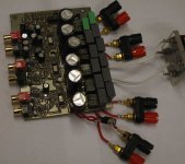
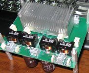

Nice pics, what caps are you using for the coupling caps?
LOL, non-audiophile caps: 10uF 16V X7R
LOL, non-audiophile caps: 10uF 16V X7R
That's what I thought 😀
I hope you can measure the system to make sure they aren't affecting the performance!
That's what I thought 😀
I hope you can measure the system to make sure they aren't affecting the performance!
I am of two minds on that subject.
If I had the equipment to measure and investigate then I would compare these with films.
I would also investigate Radiated Susceptibility (now labeled the politically correct term Radiated Immunity 🙂 ) to see if the larger volume of cap picks up more "stuff".
But right now I will stick with the "sounds good to me, why change it?"
Aren't opinions are great?
🙂
I don't think you have to worry about radiated pick up. A small film in parallel with a decent lytic will do fine. The TPA will hit 0.000x% distortion figures at low power. X7Rs are known to be non linear and you do not want to limit the performance of the chip with bad cap choices. Either way if the cap injects decent amount of 2nd and 3rd harmonics who's to say that you won't prefer that?
Last edited:
X7R's are non linear. (therefor not good for active filtering IMHO)
I would only expect the capacitance to change when the voltage across it changes.
So the only time I expect that to make a difference is when the change in Xc is significant to the input impedance of the IC.
This I would expect at low frequencies. But maybe not so much.
I am going to assume 0R for source impedance.
Let's take 60Hz. Xc for 10uF @ 60Hz is about 265.25 ohms
With the 10K IC input that is 10003.52 ohms total input Z and 99.96484 % of the signal at the IC input.
If the voltage across the cap caused a C change by -10% ( just a number for now) to 238.73ohms then total input Z would be 10002.85 ohms resulting in 99.97152% of the signal at the IC input.
This is a change of .00688% of the signal at the IC input. For a capacitance change of 10%.
On one capacitance vs voltage chart a change of more than 10V was required to change the capacitance by 10%.
The amount of signal present across the cap at 60Hz is only about 2.5% of the input drive.
The input drive for this amplifier is limited to 7Vp-p. (3.5Vp)
Let's use that number.
2.5% of 3.5Vp is about .092Vp
How much capacitance change can occur on a X7R cap as a result of a voltage change of 0.092Vp?
I do not think my woofers (nor my ears) will be able to notice the difference.
This is what I think and why I am not concerned with my choice of input cap type.
🙂
Last edited:
Well if you feel comfortable using them in what is to be considered a hi fidelity application then that's fine by me. We're talking 0.000x% distortion here, it only takes a minute variation in the signal to start increasing distortion.
Even if it's just 1% of a change of that 0.092V that's 0.025% of the original signal. Low% indeed, but the amplifier is capable of significantly higher performance than that. I hope the performance isn't degraded by the X7R coupling caps. TI use X7Rs in some of their TPA311X series evaluation modules, but chose to use lytics for the TPA3251 board.
How much capacitance change can occur on a X7R cap as a result of a voltage change of 0.092Vp?
Even if it's just 1% of a change of that 0.092V that's 0.025% of the original signal. Low% indeed, but the amplifier is capable of significantly higher performance than that. I hope the performance isn't degraded by the X7R coupling caps. TI use X7Rs in some of their TPA311X series evaluation modules, but chose to use lytics for the TPA3251 board.
Well if you feel comfortable using them in what is to be considered a hi fidelity application then that's fine by me. We're talking 0.000x% distortion here, it only takes a minute variation in the signal to start increasing distortion.
Even if it's just 1% of a change of that 0.092V that's 0.025% of the original signal. Low% indeed, but the amplifier is capable of significantly higher performance than that. I hope the performance isn't degraded by the X7R coupling caps. TI use X7Rs in some of their TPA311X series evaluation modules, but chose to use lytics for the TPA3251 board.
Well, try to achieve a distortion level as low as possible in an amp design is an admirable goal. It is a great intellectual challenge. No problem with that. However, let's not forget down stream of the amp are the speakers. We all know what kind of distortion figures that even the "best speakers" display. Our ears (or brain) most probably would not discern whether the distortion of the amp has increased by 0.01 or 0.05%?
Regards,
6 channel version.
This lets me use the TPA3251 in my main system on the three main drivers. It sounds excellent. 😀
Hi,
Do you have crossovers between the amplifier and the drivers? If not, you might want to try eliminating the output filter from the amplifier, as per the TI whitepaper on eliminating the Class-D output filter.
I've done this on my TAS5548/TAS5614 amplifiers, works great.
Cheers,
Mike
- Home
- Amplifiers
- Class D
- TPA3251d2