5th element, you have proofed that, with respect to the developers and engineers, there are critical points in the way of implementation which may lead in"subperformance" by just implementing the IC in a common way. Seeing a huge difference in k2 by varying the ps-connection from 10 to 50cm isn't "top notch", don't you think?
For sure, an eye must kept on a good layout and implementation but should we care if the complete implementation is 0.02 or 0.04 then?
In a car analogy this reminds me on an old fashioned racecar (like a 240) build and tuned to the max but difficult to handle in either driving and performance way. From my own experience, that's an expensive business.
Indeed that isn't optimal in any way, but it only really manifests at higher power levels if a decent power supply is used and at low frequencies. If an MLCC is going to degrade the performance at all power levels and across all frequencies then I'd consider it a problem. Your measurements do indeed show that decent X7Rs will give satisfactory performance, though it does require some testing to get right.
The distortion is also only 2nd order and every other harmonic remains pretty much unchanged. If the cap were to botch the other harmonics too then that I would also consider it a problem.
For most of my listening I only use 1 watt or even less. This is the area I am most concerned with optimising, keeping the low output levels linearity high, right down to 1/10th to 1/100th of a watt etc. Of course I want it to remain linear for higher power levels too.
I can't tell if you've got the copper pour on the top layer connected to anything or not, but it's worth tying it to the ground plane on the reverse side too.
What is this round thing on the power input, a filter?
The bootstrap caps should not be connected by via, but on the chip side with as small as possible current loop. You also got big current loops on the output filter, why using such big capacitors there?
The bootstrap caps should not be connected by via, but on the chip side with as small as possible current loop. You also got big current loops on the output filter, why using such big capacitors there?
Last edited:
The better lead free solder formulas performance quote well here.
We use Sn99Ag0,3Cu0,7NiGe called Sn99Ag+ from Felder:
http://www.felder.de/produkte.html?...wnloads/kataloge/NiGe-Elektroniklote - En.pdf
Compared to what if I may ask ? Not to leaded solder I hope ? Still wins hands down in many aspects.
Compared to every other lead free solders I tried - it's much better (to me) (Due to lower temperature and better flow and wetting)
Leaded is "always best" but we can't use it in daily production or customer hardware. (We actually only use it for in house, especially wired connections)
You should give it a try, but 0.5mm max, the 1.0mm+ doesn't got enough flux embedded to work without additional soldering paste. (Ever heard of "edsyn"? -> Edsyn FL22R)
Last edited:
(Ever heard of "edsyn"?
that old guy was my neighbor, anyway he invented some pump thingy for de-soldering. always copied but never better'd
Oh am I glad we don't have to use it in DIY devices. The horror.
Don't know the edsyn but will look it up.
Don't know the edsyn but will look it up.
TI do in fact via to the bootstraps on their evaluation module. Granted the chip side connection is made directly to the cap, but the other side is routed via the reverse side of the PCB.
Oh am I glad we don't have to use it in DIY devices. The horror.
Don't know the edsyn but will look it up.
I use Edsyn solder myself although it's a lead based on. Part number SS5250, works really well. I wont ever use lead free unless I have to, of the stuff I've tried it's appalled me at how bad its been, although having seen Docs recommendation I may try some other stuff.
Thing is any semi decent lead based stuff works really well, getting a nice lead free mix seems to be like finding hens teeth.
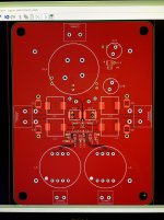
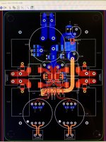
Round #2.... Hopefully an improvement over my last 'sub optimal' attempt 😛
130mm x 100mm. Supply @ 15V. I only need a couple watts.
Nice. Are those spots for Cinemags on the input?
XRK971 - Thanks for the reminder 😀 I will be using the Cinemag Transformers for this board.
5th Element - Planes 1,3,4 are pours tied to ground @ the 4-pole Cap. Plane 2 is used as the 0V pour and also tied to the 4-pole GND.
DoctorEvil - The large round ic is a 'woeful' mundorf 4-pole 35mm cap. I changed the LC 1uf filter cap to a MKP10 100V. This should decreased the loop area. I agree, the other cap was silly large. Using vias for the bootstrap circuit is a necessary evil. I am not a big fan of the TPA3251D2's pin layout.
I have attached the latest reversion with the WIMA MKP10 and WIMA 2824 PPS in the LC Filter Position.
Attachments

Last edited:
What's not to like about the pinout? It's rather functional as far as I am concerned.
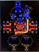
Here is my layout of the power side.

You'll notice that the power hasn't been completely routed as I used thick wire to do this. I wanted to keep the ground plane completely free and didn't want to route the power lines up and around the inductors.
My only gripe about the chip is that it's been built around a 44 pin package. It's tiny, especially vs the heatsink size, so why not make it 46, 48, or 50 pins etc?
It would be great if all of the pins on the power side were doubles, if not triples in places. I'd argue for doubles on every output pin and triples on the power and ground pins.
Either way there's nothing I have particular issue with with regards to the pin out itself, just the space constraints due to the tiny package.
Here is my layout of the power side.
You'll notice that the power hasn't been completely routed as I used thick wire to do this. I wanted to keep the ground plane completely free and didn't want to route the power lines up and around the inductors.
My only gripe about the chip is that it's been built around a 44 pin package. It's tiny, especially vs the heatsink size, so why not make it 46, 48, or 50 pins etc?
It would be great if all of the pins on the power side were doubles, if not triples in places. I'd argue for doubles on every output pin and triples on the power and ground pins.
Either way there's nothing I have particular issue with with regards to the pin out itself, just the space constraints due to the tiny package.
Attachments
happyrabbit, when you are testing this amplifier with transformer drive, keep in mind that the 3251 is four separate amplifiers. (TDA3116 is diff input)
If there is an imbalance in the input impedance there will also be an imbalance in the drive to each amplifier in the pair since there is no GND reference for your drive.
It is probably not significant but I would be interested in knowing that the outputs of the pair have the same voltage swing.
🙂
If there is an imbalance in the input impedance there will also be an imbalance in the drive to each amplifier in the pair since there is no GND reference for your drive.
It is probably not significant but I would be interested in knowing that the outputs of the pair have the same voltage swing.
🙂
happyrabbit, when you are testing this amplifier with transformer drive, keep in mind that the 3251 is four separate amplifiers. (TDA3116 is diff input)
If there is an imbalance in the input impedance there will also be an imbalance in the drive to each amplifier in the pair since there is no GND reference for your drive.
It is probably not significant but I would be interested in knowing that the outputs of the pair have the same voltage swing.
🙂
That's a good point. TI warned against that and said that signal imbalances could easily impair the system performance.
One solution would be to put (you don't have to populate the part) a capacitor from the centre tap of the transformer secondary to GND.
I wonder how good 56k modem transformers will do here. 🙂 (It's not Cinemag nor Lundahl but hey.. 😀 )
Those:
P3356 - ETAL - TRANSFORMATOR, V.90, 56K | Farnell element14 Deutschland
Datasheet: 10Hz-55kHz (-3db)
A friend measured those to:
distortion at
1khz 0,024%
100hz 0,06%
sweep -3db at 18 hz

Source: alfsch@stromrichter.org
@5th element,
would you mind that the following will do at the 3251 as well:
http://www.versatilepower.com/Images/press/New_Concept_Class.D.Audio.Amplifiers.VP.pdf
If so, i'd do a "super-reduced" layout like 50*50 with forced cooling in a cube design.
MSD1583-103MEB would fit the bill for up to 10-12A per winding. 🙂
Those:
P3356 - ETAL - TRANSFORMATOR, V.90, 56K | Farnell element14 Deutschland
Datasheet: 10Hz-55kHz (-3db)
A friend measured those to:
distortion at
1khz 0,024%
100hz 0,06%
sweep -3db at 18 hz
Source: alfsch@stromrichter.org
@5th element,
would you mind that the following will do at the 3251 as well:
http://www.versatilepower.com/Images/press/New_Concept_Class.D.Audio.Amplifiers.VP.pdf
If so, i'd do a "super-reduced" layout like 50*50 with forced cooling in a cube design.
MSD1583-103MEB would fit the bill for up to 10-12A per winding. 🙂
Attachments
Last edited:
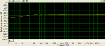
small transformers fall apart when volt*seconds get larger Eg high signal level and lower frequencies, sure you can just about dial in good numbers with lower impedances and smaller drive, <data scale> at -45dB
try -3 or -6dB at 30Hz with low distortion, maybe not good distortion
try -3 or -6dB at 30Hz with low distortion, maybe not good distortion
Last edited:
Specially for the TPA3251D2 I would go for a transformer with secondary center tap.
or you take 2 of these cheap xformers per power amp.
The primary windings in series to increase allowable level.
Each sedondary drvives one half bridge.
And the winding orientation antiphase to compensate external magnetic flux pickup. (humbucker!)
or you take 2 of these cheap xformers per power amp.
The primary windings in series to increase allowable level.
Each sedondary drvives one half bridge.
And the winding orientation antiphase to compensate external magnetic flux pickup. (humbucker!)
Last edited:
- Home
- Amplifiers
- Class D
- TPA3251d2