5th element: nice glamour shots (dust notwithstanding). Never saw glowing feet before - cool effect. You have tons of room in there for your own DSP or in our case, a couple of miniDSP 2x4's.
5th element: nice glamour shots (dust notwithstanding). Never saw glowing feet before - cool effect. You have tons of room in there for your own DSP or in our case, a couple of miniDSP 2x4's.
Well the preamp above has all the DSL stuff inside 😉
Oh, I still have my 2x6 DSP project (with additional spdif/cinch digital-in) in 50x50mm on the Desk. 🙂
Seems that these chips are now more commonly available, I just got a shipping note from TI and they are now available at Digikey (weren't there when I checked 2 weeks back).
If I finish a couple of other unrelated PCBs over the weekend I will knock up a PCB for a 2.1 FAST system and post next week. I hope it's OK to use some of the design / implementation ideas in this thread (and I have a few ideas of my own).
If I finish a couple of other unrelated PCBs over the weekend I will knock up a PCB for a 2.1 FAST system and post next week. I hope it's OK to use some of the design / implementation ideas in this thread (and I have a few ideas of my own).
Any progress to report?
I'm about to receive my samples from TI.
For a stereo amp project, I'm deciding between the TPA3251D2 chip and a conventional IRS-2092 + IRFI4020 combo.
Hope someone is able to share measurements and experiences with the TPA.
I'm about to receive my samples from TI.
For a stereo amp project, I'm deciding between the TPA3251D2 chip and a conventional IRS-2092 + IRFI4020 combo.
Hope someone is able to share measurements and experiences with the TPA.
I see that TI say the TPA3251D2 "works seamlessly with high-performance DAC's such at TI's PCM5242"
Anyone building a PCB with this combo? Should be killer!
Anyone building a PCB with this combo? Should be killer!
I have also received my samples and currently knocking up a Kicad schematic for 2.1 system for a desktop / satellite sub setup which this chip seems very suited for (although slightly less performant when using SE mode for the L+R). At the moment just thinking through how to set gain for 3 channels in the front end buffers (the sub input needs to be converted to balanced to run BTL) as this chip has no overall gain control. Once I work this out I'll post a schematic.
I'm about to receive my samples from TI.
For a stereo amp project, I'm deciding between the TPA3251D2 chip and a conventional IRS-2092 + IRFI4020 combo.
Hope someone is able to share measurements and experiences with the TPA.
Hi,
I have both IRS2092 and TPA3116,
both are fully upgraded (capacitors changed, etc...)
the amps are driven with connexelectronic.
What I can say is IRS2092 sounds better, it is clearly audible in high frequencies.
But for me (and I know it is the same for some people, and not for others) there is a kind of listening 'fatigue'
Also, it is pretty hard to reduce shuffle sound from the IRS2092 amp. I removed the ground loop and the shuffle is lower, but still present (but not audible from 1m of the speakers).
mainly for the first reason, I prefer the TPA3116. But it is my own choice.
HiHi,
I have both IRS2092 and TPA3116,
both are fully upgraded (capacitors changed, etc...)
the amps are driven with connexelectronic.
What I can say is IRS2092 sounds better, it is clearly audible in high frequencies.
But for me (and I know it is the same for some people, and not for others) there is a kind of listening 'fatigue'
Also, it is pretty hard to reduce shuffle sound from the IRS2092 amp. I removed the ground loop and the shuffle is lower, but still present (but not audible from 1m of the speakers).
mainly for the first reason, I prefer the TPA3116. But it is my own choice.
If you please,
What kind of IRS2092 module do you use? Same for the TPA3116 module.
Thank you!
5th element was so kind to measure my blue implementation of the TPA3251D2. There were some trade offs in audio performance due to the use of noname MLCC in the signal chain. The inductors also have some impact on the THD measurements. (Coilcraft MSS1210 vs ICE, where ICE were bit better) All in all somewhere below 0.01-0.1% THD unloaded but can be optimized to 0.001% with ease if needed. (If someone care about this low THD below 200Hz)
So the chip is able to perform very well and is dead silent.
I actually use them for a small PA (15" Bass + 2x8" Fullrange + 2x1" Horn tweeters in a 2.0 Mono arrangement and DSP)
For the revision I'll add FKP for the signal chain (beside the possibility of using MLCC - Murata parts works definitely better than the nonames) and a power supply supervisor.
All in all, works as expected. 🙂
Last edited:
Hi
If you please,
What kind of IRS2092 module do you use? Same for the TPA3116 module.
Thank you!
I have the L15D from ljm (capacitors changed)
and the YJ TPA 3116D2 blue board (capacitors & inductors changed)
Attached is a schematic of my TPA3251D2 amp - 2.1 for satellite speakers and subwoofer.
A couple of notes:
1) Although the TPA can do a 2.1 in one chip, the SE performance isn't as good and I hate speakers being driven through large electro caps. So this design has a dedicated sub amp in PBTL mode.
2) I have tried to optimize the power supply which has ended up a little complex but hopefully will have sonic benefits (eg. dedicated supplies for the opamps and regulated for the satellite L+R at 24v)
3) A turn on delay and instant off to avoid thumps, a opamp monitors the power rails and drives RESET.
4) I create the second balanced input by inverting the input opamp which also handles the input gain (the TPA only does x20 gain which isn't sufficient for line level for full power). I think this should be OK as a more optimised circuit will be a lot more complex.
Have a look and give me any feedback to optimize it.
Attachments
Attached is a schematic of my TPA3251D2 amp - 2.1 for satellite speakers and subwoofer.
A couple of notes:
1) Although the TPA can do a 2.1 in one chip, the SE performance isn't as good and I hate speakers being driven through large electro caps. So this design has a dedicated sub amp in PBTL mode.
2) I have tried to optimize the power supply which has ended up a little complex but hopefully will have sonic benefits (eg. dedicated supplies for the opamps and regulated for the satellite L+R at 24v)
3) A turn on delay and instant off to avoid thumps, a opamp monitors the power rails and drives RESET.
4) I create the second balanced input by inverting the input opamp which also handles the input gain (the TPA only does x20 gain which isn't sufficient for line level for full power). I think this should be OK as a more optimised circuit will be a lot more complex.
Have a look and give me any feedback to optimize it.
Hi,
Thanks for sharing. I was also busy making a design, mine will be a simple stereo amp in BTL.
Was wondering about the 20k pot with the 0.1uF over it, is that a volume control or some kind of filter? You might want this part of the drawing a little more space as it's a bit difficult to read now.
Nice idea to use split power supply, but I'm not so sure this will work safely as now all inputs are referred to -12V instead of ground. Why not a simple big single supply of 24-36 volts and one huge ground?
Looks like U1 is being powered with a LM317, maybe not enough current available. Or I misread what's being done here?
For the signal inverter, using 1k resistors instead of 10k will give you less noise. The op-amp you selected can drive 1k with no problems. Alternatively, you can consider a OPA-1632 to drive the amp for a somewhat cleaner layout.
Later this week I will share my design.
Rob
Cyenne Audio
Hi Rob, thanks for the feedback. Do share your design when ready.
Sorry it is hard to read, I'll spread out the text and repost. The caps are 0.1nF and reduce gain at higher than audio frequencies (although not ideal as the gain changes with the pot - but the pot is set and forget and same setting for both channels).Was wondering about the 20k pot with the 0.1uF over it, is that a volume control or some kind of filter? You might want this part of the drawing a little more space as it's a bit difficult to read now.
Yes all inputs are referred to -12v but as the inputs are isolated and input to the TPA is isolated via cap it should be OK. I am using the LM4562 as I have a number of spares and these are dual supply. I could setup a virtual ground for them but as I use a split supply I can use dual rails + a real ground. It also keeps the ground currents separate. However if there are sonic reasons why this is bad (especially for the TPA chips where -15v is the ground) I'll reconsider. Turn on/off mute is important as the input caps will be biased to the -12v railNice idea to use split power supply, but I'm not so sure this will work safely as now all inputs are referred to -12V instead of ground. Why not a simple big single supply of 24-36 volts and one huge ground?
U1 will be low power driving a pair of sensitive full range drivers running on a desktop near-field and rolled off below 120Hz so are unlikely to need more than 5w per channel (transients will be supplied from the power caps located close to U1's power rails). 1.5A @ 24v should be fine, and U1 will benefit from a regulated low noise power supply.Looks like U1 is being powered with a LM317, maybe not enough current available. Or I misread what's being done here?
I have lots of spare LM4562s that I want to use. 1K instead of 10K is a good tip, I'll change them.For the signal inverter, using 1k resistors instead of 10k will give you less noise. The op-amp you selected can drive 1k with no problems. Alternatively, you can consider a OPA-1632 to drive the amp for a somewhat cleaner layout.
Last edited:
Wow, the schematic is really pretty hard to read. Things look more complex than they should.
Beside this, good work. 🙂
Beside this, good work. 🙂
Sorry about the Kicad schematic, I have adjusted it to make it a little more readable. Zooming when reading the PDF will help.
Keep in mind this is 2 amps in 1, I have elected to use 2 TPA chips to gain a little more performance for the stereo pair running BTL compared to SE however complexity has suffered (also implemented a better power supply in keeping with the better performance of the TPA in BTL mode).
A single TPA in 2.1 mode would be obviously a lot simpler - at the expense of a bit more distortion with SE mode. I'm contemplating changing it back as its likely I won't be able to hear the difference anyway.....
Do have another look at the attached and let me know if you see anything I may have forgotten before I commit this to a PCB.
Attachments
Last edited:
Sorry about the Kicad schematic, I have adjusted it to make it a little more readable. Zooming when reading the PDF will help.
Do have another look at the attached and let me know if you see anything I may have forgotten before I commit this to a PCB.
Hi, I still have my doubt about the split supply. One of the things I would worry about is that the -PSU is now directly in the signal path as the drive signal is referenced to GND by the op-amp stage, but at the TPA it's referenced at -V.
Any ripple or other junk in -V will get into the signal. In practice might not be so bad as the input is balanced so should mostly cancel out, but some chance of oscillation if the impedance of the -V return is high...
And like said before, this design is hugely complex for the relatively modest power you seek. I do understand the desire not to have e-caps in the LS output...
Rob
I'm not sure if i would want potentiometers in my feedback-line without dc-decoupling.
You may want to add a bit more hysteresis to your "voltage supervisor".
You may want to add a bit more hysteresis to your "voltage supervisor".
Thanks guys for the feedback, its appreciated.
I will go back and re-think the power supply and simplify with a single supply, and use a virtual ground reference for the opamps (along with dc input decoupling).
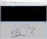
Regarding the voltage supervisor (manages RESET to avoid turn on / off thumps) the diodes provide the hysteresis - unless I'm missing something else. Attached is a simulation that shows this working.
I will go back and re-think the power supply and simplify with a single supply, and use a virtual ground reference for the opamps (along with dc input decoupling).
Regarding the voltage supervisor (manages RESET to avoid turn on / off thumps) the diodes provide the hysteresis - unless I'm missing something else. Attached is a simulation that shows this working.
Attachments
Last edited:
Thanks guys for the feedback, its appreciated.
I will go back and re-think the power supply and simplify with a single supply, and use a virtual ground reference for the opamps (along with dc input decoupling).
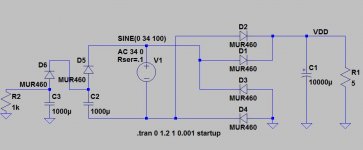
No need for virtual ground for the OPA's even if you use single winding transformer... (Left side is the output for the negative supply, the 1k R is the load for the model only)
Attachments
- Home
- Amplifiers
- Class D
- TPA3251d2