Specially for the TPA3251D2 I would go for a transformer with secondary center tap.
or you take 2 of these cheap xformers per power amp.
The primary windings in series to increase allowable level.
Each sedondary drvives one half bridge.
And the winding orientation antiphase to compensate external magnetic flux pickup. (humbucker!)
Voltage distribution using series primaries is at the mercy of secondary loading when using two separate transformers.
Separate transformers with series primaries (or even parallel primaries) is not the solution to balancing the secondary side drive.
Interesting option, thanks for the input. Would guess, I get 10 of them for the price of one Cinemag.
Testing the 3251 outdoors together with 2x 3132. 3251 is hooked up to the 15" bass, while 1x 3132 is powering the 2 fullrange drivers + 1x PBTL for the 12" "bassfill".


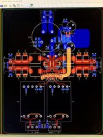
DUG Thanks for the Heads UP  I have attached the latest using the LL1592. PCB SIZE : 120mm x 150mm.
http://www.lundahl.se/wp-content/uploads/datasheets/1592.pdf
DoctorMord Luv the moblie setup !
I have attached the latest using the LL1592. PCB SIZE : 120mm x 150mm. http://www.lundahl.se/wp-content/uploads/datasheets/1592.pdf
DoctorMord Luv the moblie setup !
Attachments
Thanks mate. It clearly can be seen, that the sub didn't fit right onto/into the trailer. 😀
Will need to make a new enclosure as the actual is far from optimal. (to low tuned frequency, to much volume, to big vent..)
Edit: You ain't intend to use a heatsink at all?
Will need to make a new enclosure as the actual is far from optimal. (to low tuned frequency, to much volume, to big vent..)
Edit: You ain't intend to use a heatsink at all?
I thought I read somewhere that a heat sink was mandatory on this chip but I went back to the data sheet and could not find the reference to that.
However.
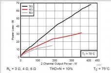
At 150deg C max and 24.4deg C/W (junction to board) and 25 C ambient.
That results in a maximum of about 7W of power dissipation.
Based somewhat loosely on Figure 7, it would be best to watch your output power when running without a heat sink.
🙂
However.
At 150deg C max and 24.4deg C/W (junction to board) and 25 C ambient.
That results in a maximum of about 7W of power dissipation.
Based somewhat loosely on Figure 7, it would be best to watch your output power when running without a heat sink.
🙂
Attachments
I just found this lovely natural convection heat sink while enjoying Monday Night Football (plus a couple beers  )
)
https://www.alphanovatech.com/dxf/N.pdf
I plan on using the N19-25B Model. ~16C/W. My current Speakers are 4ohm 93db. I don't need much in the way of cooling. I currently drive my speakers with an Electra Fidelity 45 Set amp.
Hologram M4 ? SPATIAL AUDIO
)https://www.alphanovatech.com/dxf/N.pdf
I plan on using the N19-25B Model. ~16C/W. My current Speakers are 4ohm 93db. I don't need much in the way of cooling. I currently drive my speakers with an Electra Fidelity 45 Set amp.
Hologram M4 ? SPATIAL AUDIO
its only mandatory if you want it to work.....
This isn't true, the chip performs absolutely fine without a heatsink you simply have to watch your power levels.
I messed about with this part with no heat sink. You can get about 20W/channel into 8R loads at 24V supply for more than 5 minutes without shutdown (TA=20C). The shutdown time drops rapidly as supply voltage is increased. It shuts down in just a few seconds at 36V.
I messed about with this part with no heat sink. You can get about 20W/channel into 8R loads at 24V supply for more than 5 minutes without shutdown (TA=20C). The shutdown time drops rapidly as supply voltage is increased. It shuts down in just a few seconds at 36V.
Nice to have some hard data.
Excellent
Thanks
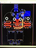
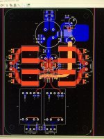
A Couple different PCB Layouts for your consideration..
A layout using the TDK ERU 25 Inductor.
http://en.tdk.eu/inf/30/db/ind_2008/b82559_a025.pdf
A layout using the Clarity TC600 85uf Capacitor.
ClarityCap TC600 Series Film Capacitor
I have also designed an amp based on the TDA7297 using this Clarity Cap.
Enjoy 😀
A layout using the TDK ERU 25 Inductor.
http://en.tdk.eu/inf/30/db/ind_2008/b82559_a025.pdf
A layout using the Clarity TC600 85uf Capacitor.
ClarityCap TC600 Series Film Capacitor
I have also designed an amp based on the TDA7297 using this Clarity Cap.
Enjoy 😀
Attachments
Why on earth are you using a 600V specified cap in such an application? And also the 100v specified mundorfs?
A Couple different PCB Layouts for your consideration..
A layout using the TDK ERU 25 Inductor.
http://en.tdk.eu/inf/30/db/ind_2008/b82559_a025.pdf
...
Too bad TDK doesn't put a L vs I graph in the data sheet.
I would add it to my list if the line looked good.
A Couple different PCB Layouts for your consideration..
..
A layout using the Clarity TC600 85uf Capacitor.
ClarityCap TC600 Series Film Capacitor
I have also designed an amp based on the TDA7297 using this Clarity Cap.
Enjoy 😀
The cap looks excellent for tube stuff but I agree with 5th element in that I question the use of a 600V cap. Even though it has an "ERS 3.0 mOhm" it is still only 85uF.
The inductors will pretty much perform like the coilcraft inductors from same dimension and type.
So an update.
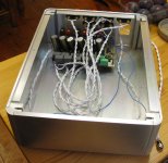
I bought a nice shiny case from Aliexpress to put this in. I was quite surprised by the affordability of this as the entire case, shipped in under a week via DHL came to around £68.
Having done a lot of my own work on aluminium, both in terms of cutting it myself, having some laser cut and also doing a lot of brushed finishes. I can say it was worth every penny.

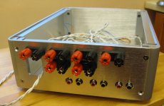
The case itself came flat-packed, with all screws and rubber feet included. Above you can see that the back panel has a cutout for an IEC connector. The case came with a fused connector too.

As you can see there is quite a lot of space left inside the case after the amplifier PCB. Mostly the width and height were required to fit in all the connectors on the back, but the length of the case was chosen specifically to allow for a suitable power supply at some point.

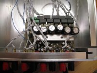
This shot gives an indication of how I've handled the heat sinking. Basically each chip has a small square of copper bar covering the thermal pad. This allows for greater separation between the chips and the heat sink above. As you can see I haven't exactly put a 'heat sink' as per say in place, but a thick aluminium bar. The bar is 15mm x 15mm, tapped with a 6mm thread in two places. This anchors the bar to the copper bar separators and keeps the chips cool. And if I need any extra performance I can easily put a heat sink on top of the 15mm bar.

With the lid on.

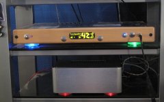
And on the Hi-fi rack, complete with colour changing illuminated feet. (Ignore the dust). The feet turn on and off when the amplifier is triggered from the preamp above.
I bought a nice shiny case from Aliexpress to put this in. I was quite surprised by the affordability of this as the entire case, shipped in under a week via DHL came to around £68.
Having done a lot of my own work on aluminium, both in terms of cutting it myself, having some laser cut and also doing a lot of brushed finishes. I can say it was worth every penny.
The case itself came flat-packed, with all screws and rubber feet included. Above you can see that the back panel has a cutout for an IEC connector. The case came with a fused connector too.
As you can see there is quite a lot of space left inside the case after the amplifier PCB. Mostly the width and height were required to fit in all the connectors on the back, but the length of the case was chosen specifically to allow for a suitable power supply at some point.
This shot gives an indication of how I've handled the heat sinking. Basically each chip has a small square of copper bar covering the thermal pad. This allows for greater separation between the chips and the heat sink above. As you can see I haven't exactly put a 'heat sink' as per say in place, but a thick aluminium bar. The bar is 15mm x 15mm, tapped with a 6mm thread in two places. This anchors the bar to the copper bar separators and keeps the chips cool. And if I need any extra performance I can easily put a heat sink on top of the 15mm bar.
With the lid on.
And on the Hi-fi rack, complete with colour changing illuminated feet. (Ignore the dust). The feet turn on and off when the amplifier is triggered from the preamp above.
Attachments

Could you give a link to that case on Aliexpress ?
It's this store.
Chassis / enclosure - Shop Cheap Chassis / enclosure from China Chassis / enclosure Suppliers at Weiliang Audio on Aliexpress.com
They have lots of nice stuff with free shipping.
- Home
- Amplifiers
- Class D
- TPA3251d2