Hi,
Do you have crossovers between the amplifier and the drivers? If not, you might want to try eliminating the output filter from the amplifier, as per the TI whitepaper on eliminating the Class-D output filter.
I've done this on my TAS5548/TAS5614 amplifiers, works great.
Cheers,
Mike
Do you happen to have a link to the "TI whitepaper on eliminating the Class-D output filter" or the actual title of it that I could search?
I would be happy to read it.
http://www.ti.com/litv/pdf/sloa023
But "Eliminating the filter also causes the amplifier to radiate EMI from the wires connecting the amplifier to the speaker. Therefore, the filterless application is not recommended for EMI sensitive applications. Methods of reducing EMI are discussed in Section 9."
This sloa isn't meant for high power with long wires.
Last edited:
the pcb is based on the tpa3251d2. digikey is stating availability in mid Nov. i like using the Mundorf 4-pole as a filter. i am using 25mm 40v 10,000uf caps to feed the chip. i am open to suggestions ?
i have compared the data sheets. clearly the tpa3251d2 is 'da chip'. i am just wondering how this translates to listening enjoyment.
interesting design, but, to me, far from optimal.
I wouldn't say my speakers are suitable for that. The tweeters certainly arent and the midrange driver isn't either. Those two have very low inductance. The woofers would be but I don't want the increased emi from having no output filter.
Well, try to achieve a distortion level as low as possible in an amp design is an admirable goal. It is a great intellectual challenge. No problem with that. However, let's not forget down stream of the amp are the speakers. We all know what kind of distortion figures that even the "best speakers" display. Our ears (or brain) most probably would not discern whether the distortion of the amp has increased by 0.01 or 0.05%?
Regards,
It seems foolish to potentially limit the performance of a high performance design simply by skimping on a couple of capacitors. After all why bother using this amplifier chip at all if you're not interested in building a design that will allow it to perform how it was intended to? TI have plenty of designs that will better suit if that's your point of view.
It seems foolish to potentially limit the performance of a high performance design simply by skimping on a couple of capacitors. After all why bother using this amplifier chip at all if you're not interested in building a design that will allow it to perform how it was intended to? TI have plenty of designs that will better suit if that's your point of view.
I do not think it is foolish at all. I understand what you are getting at. As I said in my message, it is a great intellectual challenge trying to achieve the lowest distortion. One can do it just for the heck of it, that's fine. One can also do it just to have the bragging right, that's fine too.
But I hope you can also see my point of view - if no benefits can be reaped under real live conditions, why should I do it?? We cannot listen with a scope which shows how low the distortion is. Your speakers are always the weakest link in the chain. Shouldn't one improve that first since its distortion level is orders of magnitude worse than the amp?
http://www.ti.com/litv/pdf/sloa023
But "Eliminating the filter also causes the amplifier to radiate EMI from the wires connecting the amplifier to the speaker. Therefore, the filterless application is not recommended for EMI sensitive applications. Methods of reducing EMI are discussed in Section 9."
This sloa isn't meant for high power with long wires.
Thanks for the link.
I think I will stick to full filter as my speakers are neither EMI shielded nor close to the amp.
I do not think it is foolish at all. I understand what you are getting at. As I said in my message, it is a great intellectual challenge trying to achieve the lowest distortion. One can do it just for the heck of it, that's fine. One can also do it just to have the bragging right, that's fine too.
But I hope you can also see my point of view - if no benefits can be reaped under real live conditions, why should I do it?? We cannot listen with a scope which shows how low the distortion is. Your speakers are always the weakest link in the chain. Shouldn't one improve that first since its distortion level is orders of magnitude worse than the amp?
No actually I don't appreciate your point at all, why bother using a chip of excellent technical performance, that took years of development to achieve, to only throw that hard work down the drain with poor component choices. The reason why you pick this chip over the previous generation is because of it's technical performance, why bother using it if you're not interested in getting that performance out of it?
And no, I don't see it as an intellectual challenge or curiosity in working out all the bugs in an implementation. I see it as allowing the chip to function properly and how it was intended. If their is excessive noise or distortion coming from somewhere then the design is a failure. Why? Because it's not performing how it should be doing.
If you're happy with sub standard performance then so be it. I am not.
I wouldn't say my speakers are suitable for that. The tweeters certainly arent and the midrange driver isn't either. Those two have very low inductance. The woofers would be but I don't want the increased emi from having no output filter.
Fair enough. I've used it on Seas FA22RCZ full-rangers, as well as Audax PR170M0. Even on Beyma CP21/f tweeters, although they did get quite warm...
Cheers,
Mike
EMI/RFI pollution is real
good friends don't let their friends drive filter less
Can I use the VW approach? 😀
5th element, you have proofed that, with respect to the developers and engineers, there are critical points in the way of implementation which may lead in"subperformance" by just implementing the IC in a common way. Seeing a huge difference in k2 by varying the ps-connection from 10 to 50cm isn't "top notch", don't you think?
For sure, an eye must kept on a good layout and implementation but should we care if the complete implementation is 0.02 or 0.04 then?
In a car analogy this reminds me on an old fashioned racecar (like a 240) build and tuned to the max but difficult to handle in either driving and performance way. From my own experience, that's an expensive business.
Last edited:
Edit:
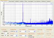
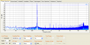
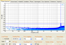
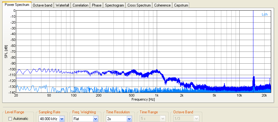
For the MLCC coupling caps, distortion depends on value/manufacturer. We tested some in the past - of course, not perfect, but good enough for the purpose we had them used (portable amp).
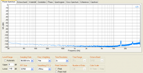
Measurements of my TPA3132D2 implementation with no load and no filter connected:
noname 1uF:

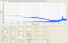
Murata 2u2F:

Murata 2u2F knocking sensitivity:

And lastly a DECT phone is dailing, 4cm above the chip, noname 1uF:

For the MLCC coupling caps, distortion depends on value/manufacturer. We tested some in the past - of course, not perfect, but good enough for the purpose we had them used (portable amp).
Measurements of my TPA3132D2 implementation with no load and no filter connected:
noname 1uF:
Murata 2u2F:
Murata 2u2F knocking sensitivity:
And lastly a DECT phone is dailing, 4cm above the chip, noname 1uF:
Attachments

Last edited:
Additionally:
Reference:

Knocking sensibility comparsion:
1uF noname:

Murata 2u2:
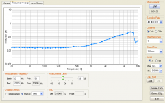
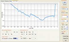
Frequency sweep at 12V, 8R+47uH load, 1uF noname coupling:


Keep in mind, that the datasheet is only showing 30dB, so only the range -35dB - -5dB is relevant.
Pretty much like the datasheet.
If acoustic noise is an issue, Murata offers low-noise MLCCs:
"Murata’s GJ8 series has been specially designed to reduce this problem and is available with capacitance between 1 and 10µF. The acoustic noise generated by 4.7 to 10µF GJ8 series capacitors represents an improvement of at least 10dB over ordinary MLCCs; for 1µF models the improvement is up to 30dB. The series is available in low-profile models with thicknesses of just 1.25, 1.60 or 2.50 mm depending on capacitance. Rated voltage is up to 50V. "
Source: http://www.electronics-eetimes.com/...coustic-noise.html?cmp_id=7&news_id=215800711
Reference:
Knocking sensibility comparsion:
1uF noname:
Murata 2u2:
Frequency sweep at 12V, 8R+47uH load, 1uF noname coupling:
Keep in mind, that the datasheet is only showing 30dB, so only the range -35dB - -5dB is relevant.
Pretty much like the datasheet.
If acoustic noise is an issue, Murata offers low-noise MLCCs:
"Murata’s GJ8 series has been specially designed to reduce this problem and is available with capacitance between 1 and 10µF. The acoustic noise generated by 4.7 to 10µF GJ8 series capacitors represents an improvement of at least 10dB over ordinary MLCCs; for 1µF models the improvement is up to 30dB. The series is available in low-profile models with thicknesses of just 1.25, 1.60 or 2.50 mm depending on capacitance. Rated voltage is up to 50V. "
Source: http://www.electronics-eetimes.com/...coustic-noise.html?cmp_id=7&news_id=215800711
Attachments
Last edited:
they have added special soy sauce to ceramics, regular or extra crispy?If acoustic noise is an issue, Murata offers low-noise MLCCs:
aka piezoelectic effect due to barium titanate dielectrics
Nah, would guess it's a derivative of the flex joint technology. Singing MLCCs are/were a problem within mobiles/handsets.
it takes a lot of voltage swing to hear a capacitor sing.Nah, would guess it's a derivative of the flex joint technology. Singing MLCCs are/were a problem within mobiles/handsets.
you mean they add a damping layer around it ?
The effect also scales with dimension, so a 0402 needs way less swing to sing. The cap builds a spring-mass-system with the pcb, where the pcb also acts as an amplifier. I don't know exactly how they do this low-noise or flex joint , but there is information available from Murata,TDK, AVX. I once made some FEM simulations of force-cracking while soldering in the past, which leads into this advanced automotive joint technology.
leads into this advanced automotive joint technology.
Pb free solder spurs more innovation for (3 year warrantee claims) LOL
hopefully it will trickle down to consumer electronics
The better lead free solder formulas performance quote well here.
We use Sn99Ag0,3Cu0,7NiGe called Sn99Ag+ from Felder:
http://www.felder.de/produkte.html?...wnloads/kataloge/NiGe-Elektroniklote - En.pdf
We use Sn99Ag0,3Cu0,7NiGe called Sn99Ag+ from Felder:
http://www.felder.de/produkte.html?...wnloads/kataloge/NiGe-Elektroniklote - En.pdf
Last edited:
- Home
- Amplifiers
- Class D
- TPA3251d2