Doc is right. Fins that tightly packed do not produced proper convection currents between the fins and offer poor absolute performance. With such a sink adding a tiny amount of forced cooling will dramatically increase its performance. Still they will be fine for music.
...To my knowledge, the fin-profile is made for forced cooling rather than convection, so performance might not be optimal in still air as the fins are to close together, so that they heat up each other more than they can convect. Tests will show.
...
agreed
...
Is the contact surface milled/sanded as well?
Contact surface is not touched...original extrusion surface.
Debating if I should drill a small hole in the heatsink for thermocouple at centre of IC pad...I have some small thermocouples that will work.
Looking really good. To my knowledge, the fin-profile is made for forced cooling rather than convection, so performance might not be optimal in still air as the fins are to close together, so that they heat up each other more than they can convect. Tests will show.
Is the contact surface milled/sanded as well?
DUG did mention that those heat sink are for computer components, I am pretty sure they are designed with forced air cooling with mind. All CPU and GPU heat sinks need fan cooling as far as I know.
I am very curious about how one can measured "smoothness" for our purposes. It totally make sense that a "flat" surface will have higher contact surface area and provide "better" contact and therefore facilitate heat transfer. However, "smoothness" or "flatness" of a metal surface is hard to define, especially if one has seen a EM picture of them. I suspect for our purpose, the only measure will be monitoring the heat transfer indirectly by measuring the temperature of the device that is being cooled. Using a thermal grease for improving contact and heat transfer make sense.
My 2 cents.
Regards,
flatness is one thing https://www.youtube.com/watch?v=w35b12YJC1sHowever, "smoothness" or "flatness" of a metal surface is hard to define, especially if one has seen a EM picture of them
smoothness is defined by the finish processes > see lapping and polishing
flatness is one thing https://www.youtube.com/watch?v=w35b12YJC1s
smoothness is defined by the finish processes > see lapping and polishing
The concept of "flat" is simple to understand. My apology for not making my question clear enough. Are there any standards in "flatness" measurement such as those in weights and length etc.? How flat should the heat sink surface has to be before it becomes useful or unacceptable? One can polish and lap as much as one wants, the surface will look and feel smoother and smoother, but at what point is it smooth enough for heat transfer? As I mentioned earlier, does not matter how smooth a surface looks, if you examine it under a microscope or better with an electron microscope, what you see is an uneven surface at microscopic scale. Again, I raised the question how much "roughness" can one tolerate for heat sink surface? Can surface be "flat" but "rough"?
Anyway, for our purpose, the requirement is much less stringent than other scientific experiments. Typically we just monitor the temperature of the device and heat sink. If the readings are below certain numbers (whatever way these numbers are based on e.g. decomposition temperature of the device), then it is acceptable. This method is not precise, but sufficient for the purpose. However, the disadvantage of this approach is that one has to assemble everything and then measure.
Regards,
depends how much performance you need, small contact area and large dissipation (Eg high heat density) needs more performance. you can get a good idea about level of smoothness vs temp gradients finding where the knee lies, the knee will shift right as the heat density increases. reviewing some of the Cree LED and perhaps old Pentium 4 CPUs curves can you a rough idea ( no pun intended ) but this is DIY so polishing up to mirror smooth isn't a big deal IMO , the way the TIM / grease is applied is probably just as important. Take a look at all the thetas from the junction to air to decide where the point of *diminishing returns lies. In my experience adding just a little air movement trumps most other performance techniques. I wonder about the uncertainty of any measurement to gauge the true junction temp ( is there a metric provided on die?) *usually worst case theta JC and HS to air dominates the rougher interfaces.
Last edited:
http://www.ti.com/lit/ug/slvuag8/slvuag8.pdf
eval board appears to have provision for post filter feedback
eval board appears to have provision for post filter feedback
I have also seen indium foil used between contact surfaces - it is soft and conforms to surface irregularities for better conduction. If you look at surface of heat pad on chip that will give you an idea of surface roughness. Mirror smooth isn't necessarily best as you actually have more surface area with a micro roughness. There is a trade off between smoothness and ultimate hear flux. I think sanding with 600 grit paper should be smooth enough when used with thermal grease.
Interesting😎http://www.ti.com/lit/ug/slvuag8/slvuag8.pdf
eval board appears to have provision for post filter feedback
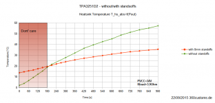
Having 8mm standoffs mounted to the board greatly affects thermal flow (stack effect):

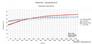
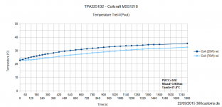
Temperatures within the MSS1210 inductors at different power levels. Actually can't explain why the inductors run cooler on higher Pout (would guess, it's due to the B-H loop hysteresis loss):


Temperatures within the MSS1210 inductors at different power levels. Actually can't explain why the inductors run cooler on higher Pout (would guess, it's due to the B-H loop hysteresis loss):
Attachments
Last edited:
Hi all,
I just started a new thread on I AM D v200 and FX audio d802.
There are hundreds of good posts on french forums.
How do you think it can sounds compared to a TPA3116 or TPA3251D2 ?
These amps are based on PWM technology and are digital only.
I just started a new thread on I AM D v200 and FX audio d802.
There are hundreds of good posts on french forums.
How do you think it can sounds compared to a TPA3116 or TPA3251D2 ?
These amps are based on PWM technology and are digital only.
Hi all,
I just started a new thread on I AM D v200 and FX audio d802.
There are hundreds of good posts on french forums.
How do you think it can sounds compared to a TPA3116 or TPA3251D2 ?
These amps are based on PWM technology and are digital only.
Hi Camelator,
It looks like a TAS5614LA closed loop PWM-input class-D in the V200. The I2S-PWM conversion is handled by a TAS5548 (could be 5538 or 5558, but all pretty much the same- it's a bit hard to read).
TAS5614LA may sound good, but TAS3251D2 is superior with 111dB DNR, 3x better noise performance and about 10x better THD.
Overall the amp is not pure digital, since the signal is converted to PWM, which is essentially analog. (Bruno Putzeys lectures have the clearest explanation of how PWM is analog). Unfortunately some marketing geniuses have propagated this classD=Digital myth.
Agree with you,
but from a digital source, there is no DAC in the path to the TAS5548 .... it can have positive impacts on the quality vs superior THD of the TAS3251D2.
Another positive argument: the cost. If you remove good DAC and good interconnects from the path, it is less expensive.
Am I wrong?
Hi Camelator,
You have a point about the cost. It may be cheaper to use a TAS5548 to combine biquads etc + DAC directly to 8 PWM outputs rather than buying 8 high-quality DAC channels. The DAC is inside the TAS5548. It's called a "DAP" but puts out a PWM (therefore analog) signal. It's appealing to system designers to simplify larger designs.
However, analog inputs like those of the TPA3251 have a greater appeal to most DIY-ers than PWM inputs. With analog there is more opportunity for creativity in the hardware side, and ultimately you can achieve a higher level of audio performance instead of a pre-defined limit set by the TAS5548 modulator.
FYI there's a thread on DIYAUDIO called "Default Digital Amplifier Project" that discusses some more TAS5548-TAS5614LA designs.
Sorry- correction: The thread is not called "default digital amplifier project" it is just "digital amplifier project". It's here:
http://www.diyaudio.com/forums/class-d/252181-digital-amplifier-project.html?highlight=tas5548
http://www.diyaudio.com/forums/class-d/252181-digital-amplifier-project.html?highlight=tas5548
Hi Camelator,
You have a point about the cost. It may be cheaper to use a TAS5548 to combine biquads etc + DAC directly to 8 PWM outputs rather than buying 8 high-quality DAC channels. The DAC is inside the TAS5548. It's called a "DAP" but puts out a PWM (therefore analog) signal. It's appealing to system designers to simplify larger designs.
However, analog inputs like those of the TPA3251 have a greater appeal to most DIY-ers than PWM inputs. With analog there is more opportunity for creativity in the hardware side, and ultimately you can achieve a higher level of audio performance instead of a pre-defined limit set by the TAS5548 modulator.
FYI there's a thread on DIYAUDIO called "Default Digital Amplifier Project" that discusses some more TAS5548-TAS5614LA designs.
Hi Frammis,
many thanks for this clear answer. As I am no good to design electronic architecture, I am staying very excited with this thread.
- Home
- Amplifiers
- Class D
- TPA3251d2