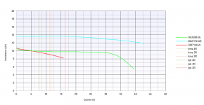
Inductors:
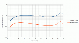
Bourns SRP1245A-100M
XAL8080-103MEB
Comparsion between some:
Lin scale:

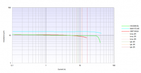
Log scale:

The simulation for the Bourns:


The chart is for full power at 2R load, so 1% inductor THD wont be that bad:

----------------------------
Did another forced cooling test - the amp is putting out ~73Wrms into 3R9 (per channel). So 146Wrms or 206Wp at the moment (continous output 1kHz). Peak performance is still better of course. (Junction temperatur, of course, is always beyond 125°C)
Bourns SRP1245A-100M
XAL8080-103MEB
Comparsion between some:
Lin scale:
Log scale:
The simulation for the Bourns:
The chart is for full power at 2R load, so 1% inductor THD wont be that bad:
----------------------------
Did another forced cooling test - the amp is putting out ~73Wrms into 3R9 (per channel). So 146Wrms or 206Wp at the moment (continous output 1kHz). Peak performance is still better of course. (Junction temperatur, of course, is always beyond 125°C)
Attachments
Last edited:
Could you provide a link...open to suggestions.
Google is your friend.
Ice Components ICE Components - Class D Inductors
I like Mr Google
COILCRAFT RFS1412 10uH 6.2A(10%L drop) RFS1412-103ME
ICE COMPONENTS 1D10A 7.5A (10%L drop) 1D10A-100M
WURTH WE-PD SMD 10uH 10.5A(10%L drop) 7447709100
ICE COMPONENTS 1D14A 11A (10%L drop) 1D14A-100M
SUMIDA CDEP 10uH 11.5A(10%L drop) CDEP147NP-100MC-125
COILCRAFT SER2900 10uH 13A(10%L drop) SER2915L-103KL
COILCRAFT SER2900 10uH 18A(10%L drop) SER2915H-103KL
WURTH WE-HCF SMD 10uH 22A(10%L drop) 7443631000
COILCRAFT SER2900 10uH 28A(10%L drop) SER2918H-103KL
ICE COMPONENTS 1D17A 31A (10%L drop) 1D17A-100M
WURTH WE-HCF SMD 10uH 34A(10%L drop) 7443641000
ICE COMPONENTS 1D23A 37.8A (10%L drop) 1D23A-100M
ICE COMPONENTS 1D31A 50A (10%L drop) 1D31A-100M
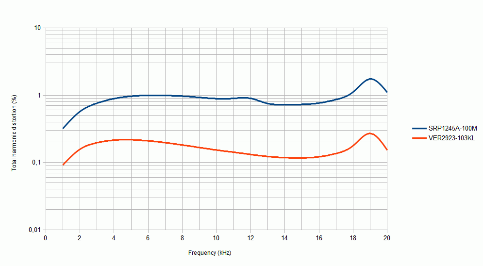
So you're also seeing a rise towards low frequencies of harmonic distortion.
With regards to the excessive chip temperature I can't help but wonder if the thermal interface pad that you are using is partly to blame. The heatslug in the TPA is connected to ground and shares the same electrical connection as the ground pins on the TPA. TI state that you should have a good solid electrical connection to PCB ground from the heatsink. I am guessing they intend for the heatsink to be in direct contact with the heatslug on the TPA without electrical isolation using some thermal paste instead.
With regards to the excessive chip temperature I can't help but wonder if the thermal interface pad that you are using is partly to blame. The heatslug in the TPA is connected to ground and shares the same electrical connection as the ground pins on the TPA. TI state that you should have a good solid electrical connection to PCB ground from the heatsink. I am guessing they intend for the heatsink to be in direct contact with the heatslug on the TPA without electrical isolation using some thermal paste instead.
So you're also seeing a rise towards low frequencies of harmonic distortion.
Are you refering to post #341 and Plot #167_12121.png?
The plot is based on simulation results made in LTSpice with only the inductor modell data.
With regards to the excessive chip temperature I can't help but wonder if the thermal interface pad that you are using is partly to blame.
I don't use a pad anymore, the heatsink is connected metall-to-metall with thermal grease only (but is not overmilled at the contacting spot). The excessive chiptemp is not mainly a concern, as the heatsink is going up "straigt" to ~85°C within 10 minutes, so it is supposed to work.
TI state that you should have a good solid electrical connection to PCB ground from the heatsink.
Would guess this is more due to EMV/EMI.
From my conversation with TI i know now, that the 175W/350W where measured in a different way. From the conversation:
The full power testing is done with a forced air system that regulates the power pad temperature to 75C. That provides a constant reference point for comparison, independent of the heatsink used. We actually drill a hole in an external heatsink and embed a thermocouple to monitor Tcase.
Which means, i actually can't reach full continous power neither by convection (with this heatsink) nor by forced cooling. Holding the power pad temperatur at 75°C is really a different story in the way of proper cooling.
But, as said, dynamic full power is possible, tested with 3R9, both channels loaded (even without forced cooling).
Even the EVM isn't capable of running full cont. output for longer periods of time. (seconds/minutes)
(Beside this, i tripped the latching OC trigger yesterday)
From the conversation:
Some automotive customers use a pink noise signal with 9dB crest factor to size their heat sinks. That is considerably easier to cool that a max power sine wave! And automotive is a very demanding application, where they do not tolerate early shutdowns.
So anyone knows a tool with selectable crest factor?
Regards.
Last edited:
...
So anyone knows a tool with selectable crest factor?
Regards.
Test Tone Generator Download
Free for 30 days
Have not tried it...just found it.
Hi Doctormord,
You might want to try an FTC power test to see how your amp might be rated if it were a consumer product. If you "pre-condition" the amp at 1/8th power for 1 hour, then you only need to test at max power for 5 minutes. You can choose some THD level (like 0.1%) at which to specify max power. Do you think you might get more than 85W under such conditions?
I'm not sure why your amp might have tripped the OC protection. The OC is cycle-by-cycle type, which needs to keep limiting non-stop for at least 2ms before a shutdown will occur. Usually the shutdown takes longer than 2 ms since you rarely clip hard enough into a very low impedance load to trip that fast. If the limiting is only happening occasionally (less than 50% of the time), an OC shutdown won't occur. However, it would shut down quite fast for a momentary short to ground.
One more thing- the TPA3251 has a speaker DC protection feature that can trip if it senses an imbalance in load currents of more than 2A or so between each half of the BTL bridge. Example: If outA is sourcing 4A and outB is sinking 2A, the DC protection will trip. This prevents speaker damage if a user connects the load between channel A and ground, for example. Shutdown time is about the same for the DC protection as it is for OC.
Thanks, tried that yesterday, the pink noise stuff didn't worked out right.
@Frammis, I wonder if TI overmilled their heatsink or if it is fully anodized.
@Frammis, I wonder if TI overmilled their heatsink or if it is fully anodized.
Overmilled, based on other high power TI EVM's like TAS5630.
Are you refering to post #341 and Plot #167_12121.png?
The plot is based on simulation results made in LTSpice with only the inductor modell data.
Ah that makes more sense.
Holding the power pad temperatur at 75°C is really a different story in the way of proper cooling.
Wow that's quite something, if completely unrealistic.
But, as said, dynamic full power is possible, tested with 3R9, both channels loaded (even without forced cooling).
Well this is good news and really all that matters.
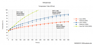
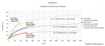
Did another measurement, now with overmilled, plained and pollished heatsink.That heatsink where in no way flat as intended, more like concav.
Tcase is measured at the contacting surface right next the IC, Theatsink is on the surface right obove the IC between the fins. These data is compared to the EVM performance, which i got on request from a super-friendly TI employee. 🙂 (Thanks for that) Case temperature at the EVM is measured with a probe embedded in the heatsink 1mm obove the chip.
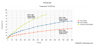
I actually can't get above 150W (Prms) as the power supply is limited. First diagram is absolute temperature, second one is relative to ambient temperature.
The measurement shows cleary how important a good thermal connection is with this IC.
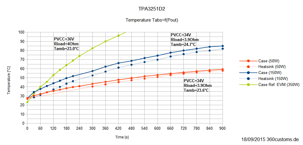


Tcase is measured at the contacting surface right next the IC, Theatsink is on the surface right obove the IC between the fins. These data is compared to the EVM performance, which i got on request from a super-friendly TI employee. 🙂 (Thanks for that) Case temperature at the EVM is measured with a probe embedded in the heatsink 1mm obove the chip.
I actually can't get above 150W (Prms) as the power supply is limited. First diagram is absolute temperature, second one is relative to ambient temperature.
The measurement shows cleary how important a good thermal connection is with this IC.
Attachments
Last edited:
Cree has papers on thermal limiting with high power high density LED arrays vs roughness of the heatsink. And yes thingsmdo need to be a lot smoother than you'd think!
Indeed. The first one especially.
I actually can't get above 150W (Prms) as the power supply is limited.
I see, now it's my turn.😉
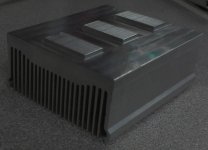
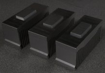
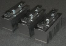
A surplus computer heatsink machined (thanks to machinist at work), then I sliced it and sanded edges.
Then I made the PCB back support (with notches for the bootstrap caps).
Install later today.
I guess I will have to build up one of my SE to DIFF boards to drive this thing.
Then the PS.
🙂
Then I made the PCB back support (with notches for the bootstrap caps).
Install later today.
I guess I will have to build up one of my SE to DIFF boards to drive this thing.
Then the PS.
🙂
Attachments
Looking really good. To my knowledge, the fin-profile is made for forced cooling rather than convection, so performance might not be optimal in still air as the fins are to close together, so that they heat up each other more than they can convect. Tests will show.
Is the contact surface milled/sanded as well?
Is the contact surface milled/sanded as well?
- Home
- Amplifiers
- Class D
- TPA3251d2