haha, good to know ^_^ Well i'm sure by the time I collect up all the components and get a design done, there will be more of them. maybe if i'm lucky, they'll even have them up for sample on the website 🙂
So no chinese boards yet? If I beat the chinese to it, i'ma do a happy dance 😉
If noone really shares a proven layout, they wont go for production. 😀
Great work guys!
It would be nice if an "auto power save" mode could be incorporated.
Or maybe an appropriate power supply with this function already exists?
It would be nice if an "auto power save" mode could be incorporated.
Or maybe an appropriate power supply with this function already exists?
Great work guys!
It would be nice if an "auto power save" mode could be incorporated.
Or maybe an appropriate power supply with this function already exists?
Well mine does my main HiFi unit turns the board on standby when not in use.
your main hifi turns on/standby your tpa amp board?
could you share info about how it's done?
Well my tpa board is microcontroller controlled, as is my preamp/dsp board. I have a wire running from one micro to the other that tells the micro on the tpa board to put the board in and out of standby whenever I switched to the loudspeakers on the pre amp.
Does your board implements a reset handler for power-loss or power-off? My actual implementation for capacitive power-on-reset solution is not pop-free when powering off by design. Need to test how much capacitance is needed for pop free power-on to limit the effect on power-off.
(Actually using capacitive pull-up with reverse freewheeling protection diode. Using just the reset pin for on/standby is pop free of course)
(Actually using capacitive pull-up with reverse freewheeling protection diode. Using just the reset pin for on/standby is pop free of course)
Last edited:
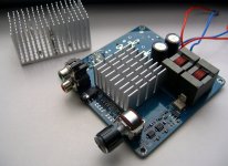
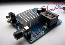
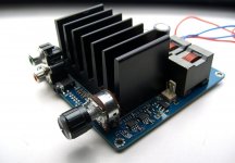
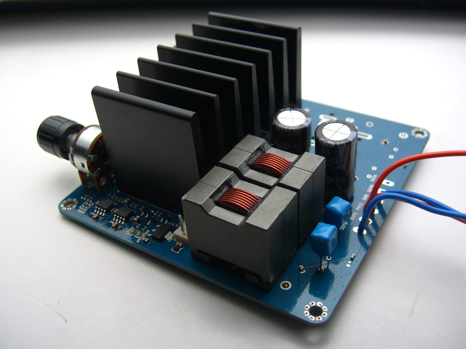
Some pics of the setup.
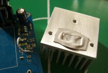
The initial thermal i used with the smaller heatsink:

The heatsink mounted to the board:


Replaced with the "real" heatsink featuring 3K/W:


The initial thermal i used with the smaller heatsink:
The heatsink mounted to the board:
Replaced with the "real" heatsink featuring 3K/W:
Attachments

Does your board implements a reset handler for power-loss or power-off? My actual implementation for capacitive power-on-reset solution is not pop-free when powering off by design. Need to test how much capacitance is needed for pop free power-on to limit the effect on power-off.
(Actually using capacitive pull-up with reverse freewheeling protection diode. Using just the reset pin for on/standby is pop free of course)
It implements a reset or power up sequence upon loss of power but nothing special for detecting a momentary loss of power, or anything special for being shut down upon loss of power.
My board is completely silent upon removal of power though without any pops or clicks. I am guessing how power is managed on your board is vital towards this though and given another design I am sure mine would splutter all over the place. If the opamps lost their supply first I am sure this would create a pop or some sort.
New PCB being built up to see if it will have any effect on the rising H2.
My first layout was more aimed at providing a completely uninterrupted ground plane. TI don't however do this and not is it their recommended layout. So we shall see!
My first layout was more aimed at providing a completely uninterrupted ground plane. TI don't however do this and not is it their recommended layout. So we shall see!
Your renders are getting better and better ;p
These are photos in a lightbox I think - too much gritty detail and bits of dust and blemsishes to be renders.
But if they are indeed renders, wow!
These are photos in a lightbox I think - too much gritty detail and bits of dust and blemsishes to be renders.
But if they are indeed renders, wow!
Agreed, and the depth of field / focus falloff is fantastically realistic if a render. Great looking amp either way!
Sent from my iPhone using Tapatalk
Dont really think they're renders, hence the emoticon. But dr Mords renders were so good that the picture and renders really look alike. With a bit better lighting it would be very difficult to extinguish
TI don't however do this and not is it their recommended layout. So we shall see!
Source?
Dont really think they're renders, hence the emoticon. But dr Mords renders were so good that the picture and renders really look alike. With a bit better lighting it would be very difficult to extinguish
Yeah, the pictures were done in a rush, but from reality with an old cam. 🙂 Lightning is done via pulled 17" notebook backlight. (Display removed)
I have quickly run through this thread, -indeed interesting!
CSTART voltage cannot be used directly to set the CM of an OPA1632 (which is preferred for input opamp over SE opamps in general), as it is not same voltage as the INPUT pins' DC level. However, the INPUT DC level is AVDD/2 and is, different from TAS5613A/30B, constant over PVDD range. The CM of the OPA1632 can be set to basically any voltage, as the AC coupling caps are still needed, if not a DC servo circuit is used.
Basically any voltage might be an issue when powering down the device, due to discharge imbalance of the coupling caps.
Last edited:
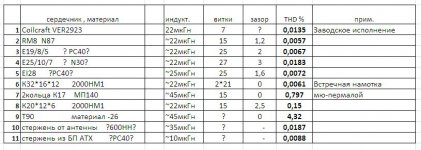
doctormord, it is a pity that you are using VER2923. The distortions introduced by these inducters is 2-3 times higher than the inductor wound on RM8 N87 ferrite.
Source, measurements, link, implementation?
The results of measurements (sorry that in Russian):
Attachments
Thanks! Don't worry, i had Russian at school. 🙂
Do you have any more information about the test arrangement?
Do you have any more information about the test arrangement?
Last edited:
- Home
- Amplifiers
- Class D
- TPA3251d2